The high popularity and low price of displays mean they are in almost every modern device, including DIY. Choosing a display for a specific application is a very important matter. Some are more or less power-hungry. Others are brighter or dimmer, which determines the possibility of using them in full sunlight. We also have different shapes. Squares, rectangles, or even
round ones. Unfortunately, young makers often forget about the aesthetics of the finished device. Having worked for almost two years in the display industry, I felt the need to explain an issue that really bothers me.
So what am I talking about?
It’s about designing the enclosure for the display. In the age of ubiquitous 3D printing, we have the ability to print a reasonably aesthetic enclosure. Unfortunately, the design of these enclosures often isn’t exactly at a decent aesthetic level. I’d even say that, in many projects, the aesthetics are a total miss. Please take a look at the photos below.
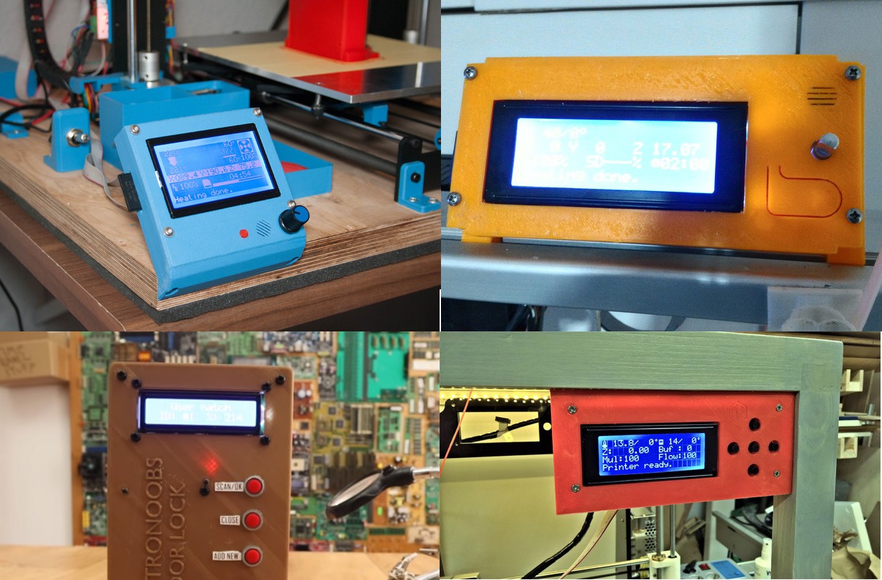
Did you notice the common feature? Yes, the metal frame exposed on the outside of the device. That frame is there to clamp the LCD glass with the conductive rubber and is not meant to be exposed externally. Have you ever seen a smartphone with a visible metal display frame? Does the display in your washing machine stick out above the panel? Do you have a monitor on your desk without a housing? No. So why are you designing your enclosures this way?! Look at examples of mass-produced devices that use the same type of displays.

It does look better, right? Let me explain how to achieve this in a very simple way.
Display areas
First, the theory. To correctly design the window for a display, we need to know the dimensions and location of several parts of the display.
-
- Outline Dimension (OD) – the external dimensions of the display. How much space the display occupies.
-
- Visual Area (VA) – the visible area of the display. This is the field you can uncover, and it won’t be embarrassing. Most often, it’s a uniform-colored glass area.
-
- Active Area (AA) – the active area of the display. This is where the pixels we control are located — hence “active”.
-
- Mounting depth – if the display module has a PCB with holes, the mounting will be based on that PCB.
- Mounting hole spacing – to determine where to place the screw holes. The holes won’t always be at the display.
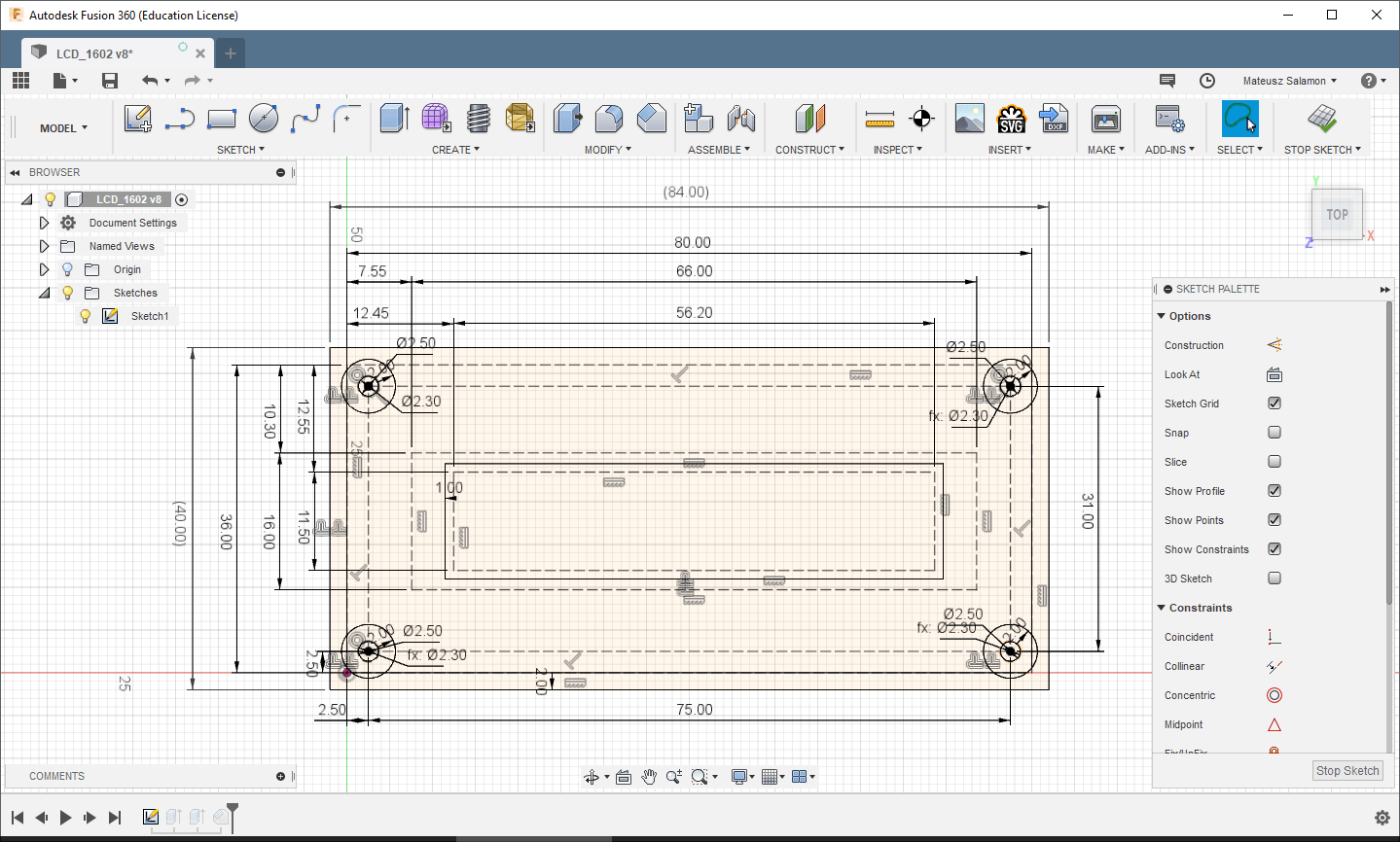
The drawing should clarify these concepts. This is the most classic 16×2 alphanumeric LCD. I marked in red the dimensions we care about.
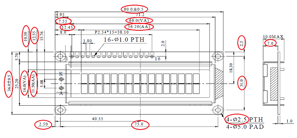
But where should the designed window be? The opening in the enclosure should:
- Reveal all the pixels, i.e., the Active Area
- Not reveal more than the Visual Area
So the edge of this window should run between VA and AA. Only and exactly there!
You can buy such a display in my store.
Grab a pencil
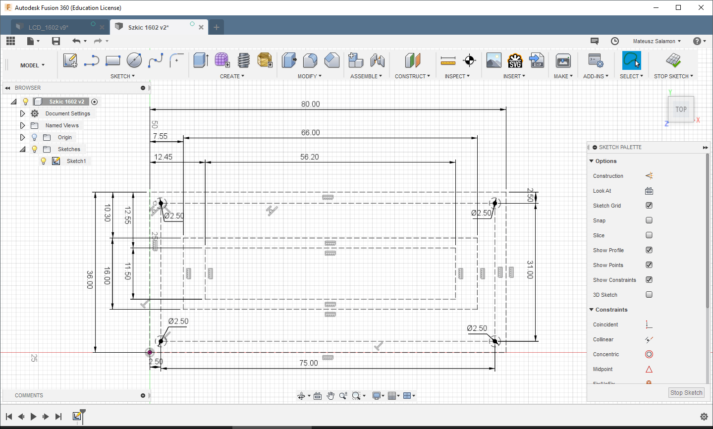
My pencil will be Fusion360. How do you handle “synchronizing” all five of the above points?
Start by drawing OD, VA, AA, and the holes in a sketch using construction lines.
Now that you’ve transferred the key dimensions to the sketch, you can start designing the enclosure. For this short tutorial, I’ll make a screw-on front.
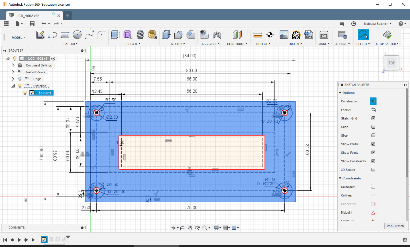
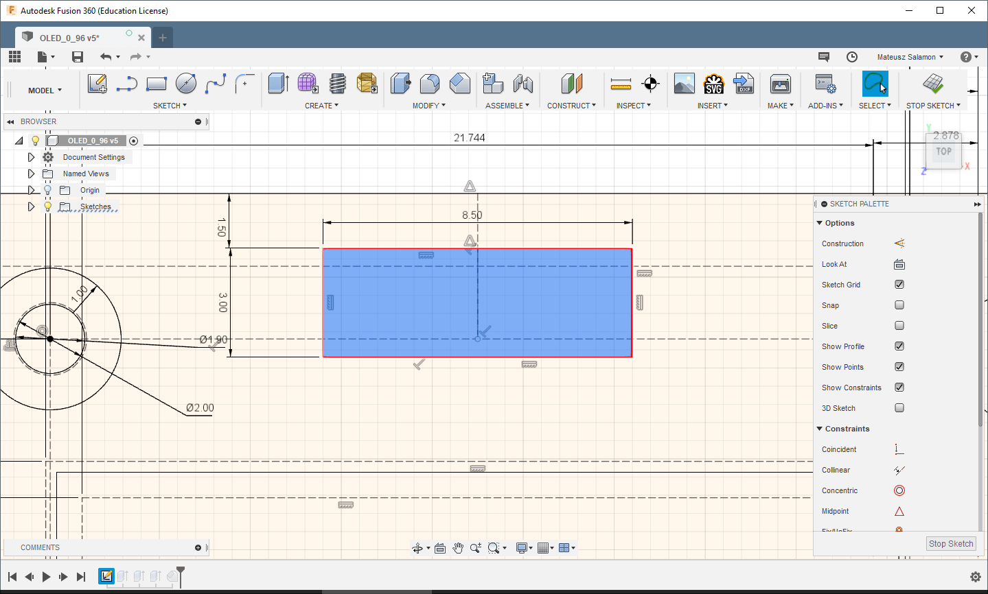
Start, for example, with the edge of the LCD window. Select the rectangle defining AA and, using the offset function, draw (now with a solid line) the window. A tip from me — it’s best if the window is larger by about 1 mm in each dimension. If the display’s AA is 56.2 x 11.5 mm, then the enclosure window is best at 57.2 x 12.5 mm. It’s fine if it’s a little larger. If the enclosure is thick, even better. However, remember that the opening in the enclosure cannot be larger than the VA, i.e., 66 x 16 mm. In my example, I set the offset to 1 mm, so the opening in the enclosure will be 58.2 x 13.5 mm.
In the next step, determine the external dimension of the front based on the display’s OD. I did this with a 2 mm offset, so my LCD cover will measure 84 x 40 mm. Of course, if this is the target enclosure, it will be the device’s front together with the final window position.
It remains to sketch the standoffs with holes for the mounting screws. The shape is basically arbitrary. I made cylinders. First, define the hole for the screw. I’ll use an M2.5 screw. Based on my tests, for holes for such a screw, you should print a 2.3 mm diameter hole. Then draw, e.g., with an offset, the outer circle to get a cylinder with a hole. A 2 mm offset from the screw hole is sufficient in this example.
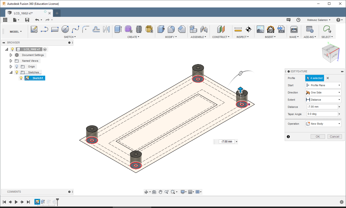
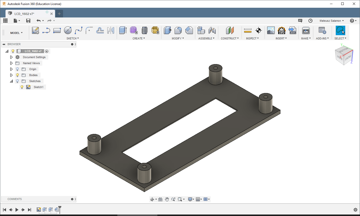
The sketch is ready. Now just extrude the solids. The first solid to extrude will be the front. Select all surfaces except the LCD window and extrude, e.g., 2 mm. Next, select all four rings for the mounting standoffs and extrude them in the opposite direction. How much? The side-view drawing of the display will tell us. We’re interested in the distance from the front edge of the metal frame to the surface on which the mounted display will rest on the designed standoffs. In the case of a classic 16×2, this will be the top side of the PCB. From the drawing, it’s 7 mm.
I also often do one more thing — I chamfer the edges of the LCD window. It’s not necessary, but it adds extra aesthetics. A 1 mm chamfer is enough. The chamfer depth is naturally limited by the front’s thickness.
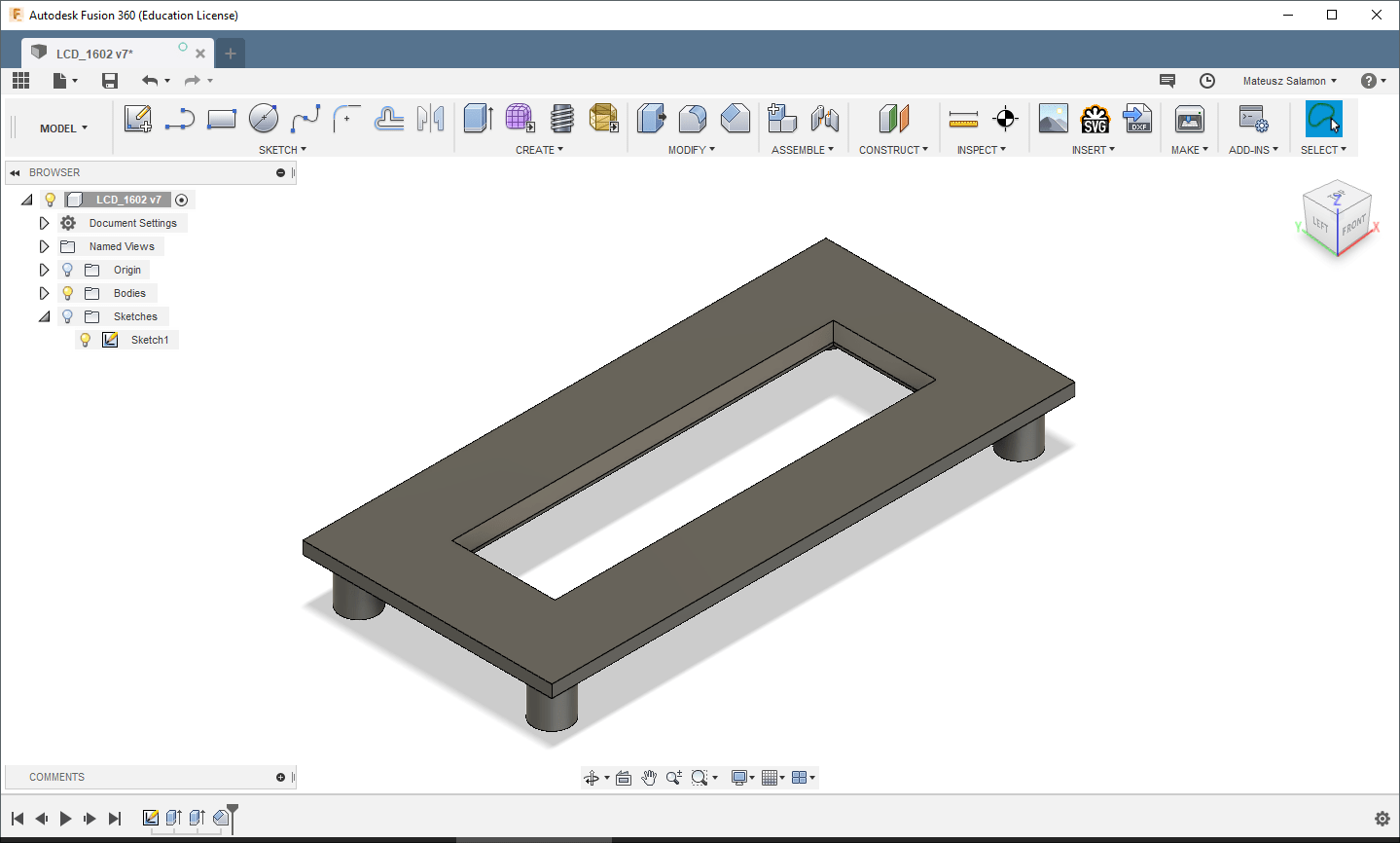
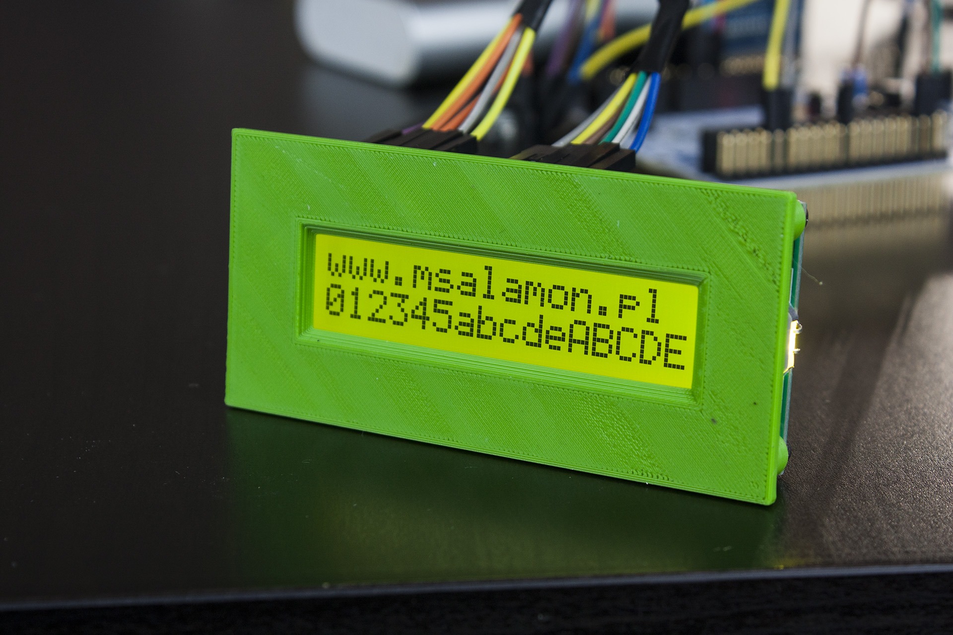
Now you can put it on the printer. The result is as follows.
Practice makes perfect
For practice, try to make a similar front for a different display. I also had on hand a module OLED 128×64 0.96″ with PCB. Once again, in short:
Sketch the module using construction lines.
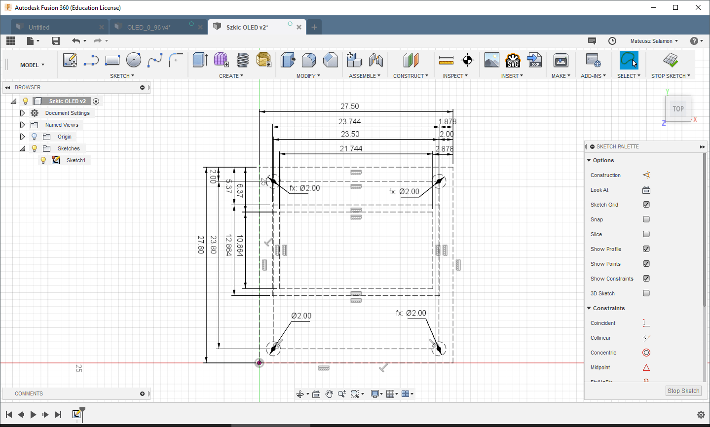
Draw the window, the external dimensions and the pillars (1.9 mm hole for an M2 screw, 1 mm offset for the pillar thickness), and extrude the front.
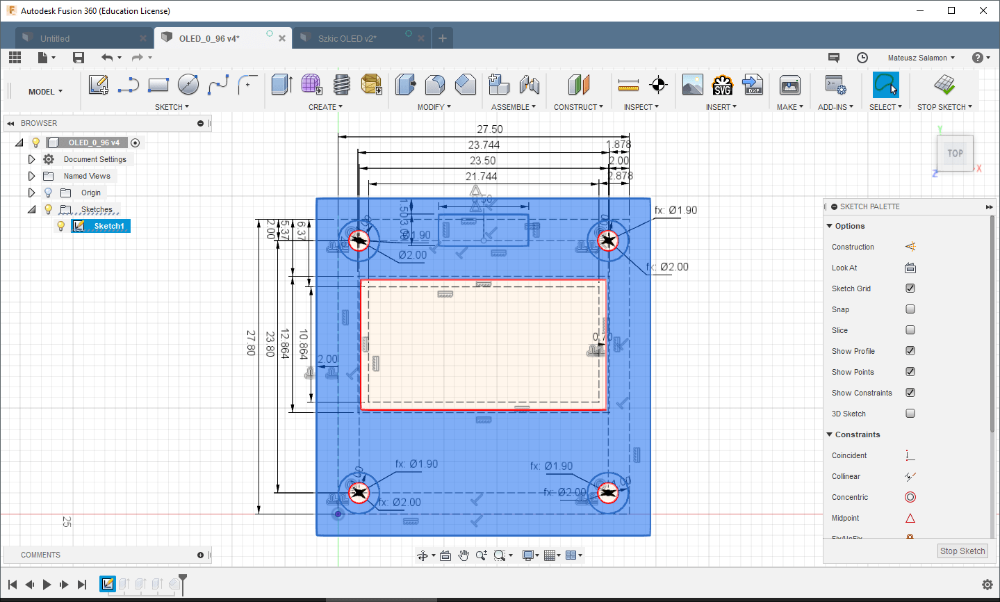
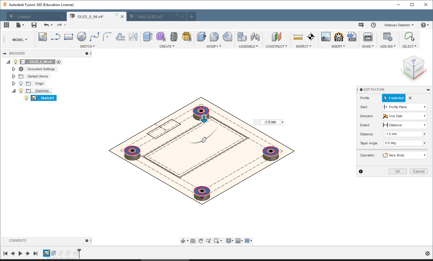
Extrude the pillars to the OLED thickness, 1.5 mm. Note! In the side view we can still see the communication pins sticking out. Unfortunately, they protrude slightly above the OLED glass. What to do in this case?
- You can ignore it, but the front may bend slightly.
- Resolder the pins a bit shallower. In mass production, such silly rework is a no-go.
- Make a subtle recess for the pins. A few hundredths of a millimeter of a pocket will do the trick here.
- Use longer standoffs. Keep in mind that the front won’t press against the front of the OLED glass in this case.
For the test print, I chose option number 3. So I cut a rectangle 0.5 mm deep under the pins.
All that’s left is to chamfer the edges and it’s done. Here’s the result.
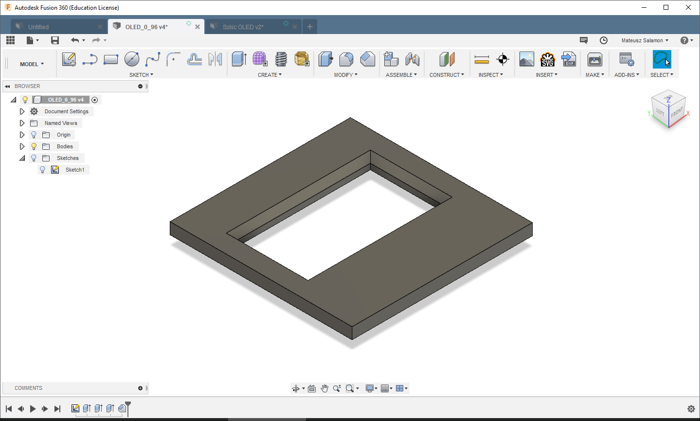
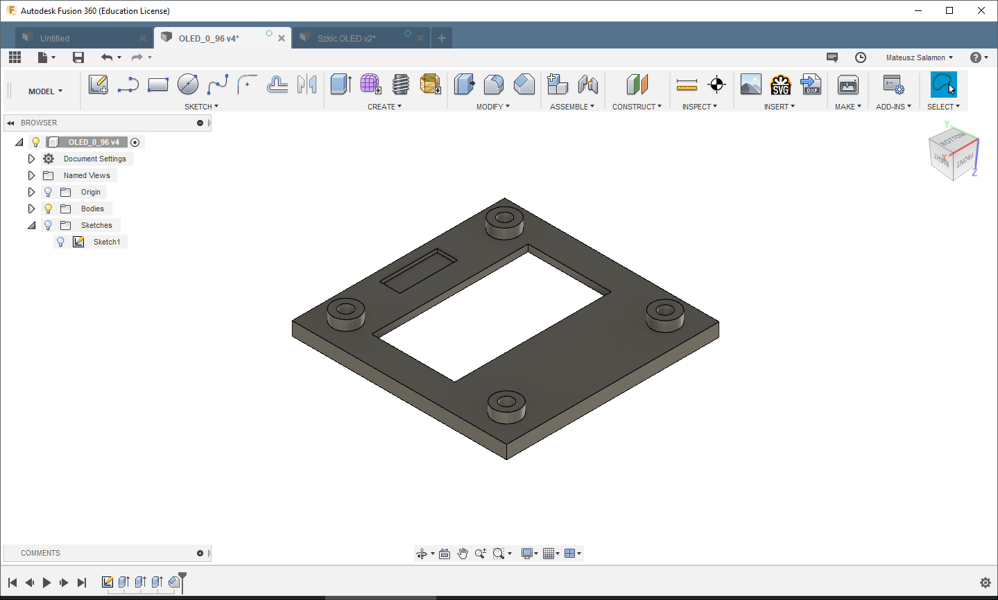
After printing:

Summary
I printed the designed fronts in PLA. The results are very good, as you can see in the photos. As you can see, designing an aesthetic front for a display is not complicated. The most important thing you need is the display’s drawing. Every seller should provide it to you. If they don’t — change the store. You can also determine the dimensions yourself with calipers. While for mono LCDs or larger TFTs this can be determined quite easily, for tiny OLEDs the measurement error with calipers can be large enough that you won’t hit the window symmetrically. It depends on how precise your hands are. Fortunately, all OLEDs on the market are almost identical, so getting a drawing is very easy.
Thank you for reading this post. If you like this kind of topic, let me know in a comment.
The models from the post are available on Thingiverse at the links: LCD 1602 and OLED
If you noticed an error, disagree with something, would like to add something important, or simply feel like discussing this topic, write a comment. Remember that the discussion should be polite and in accordance with the rules of the Polish language.
CONTEST
I wanted to organize a small contest with prizes 🙂 Rules:
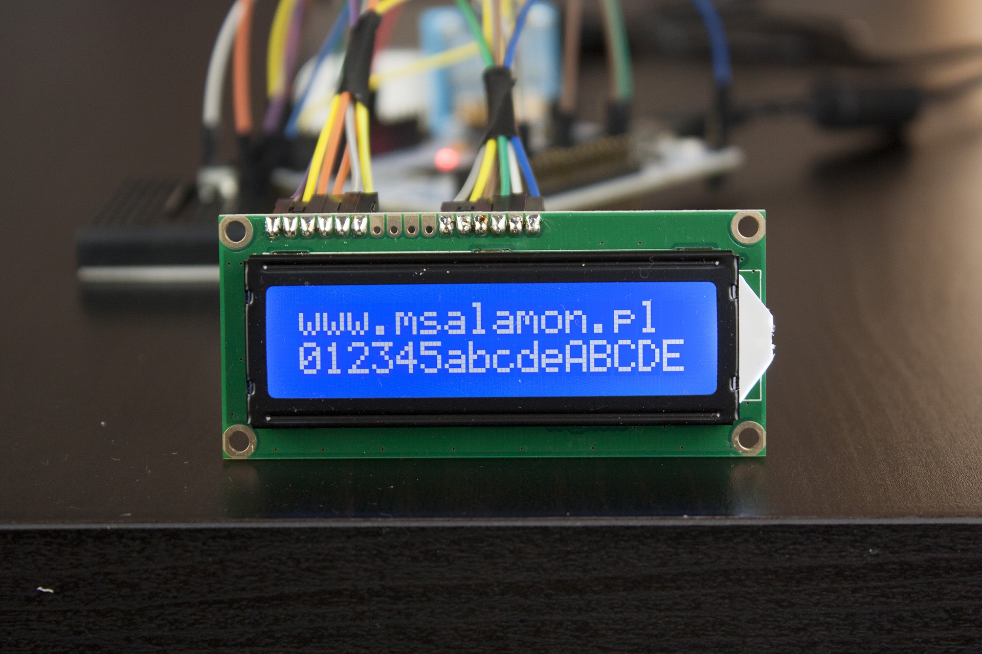
- The prize is four alphanumeric displays in the following colors:
- Blue background, white negative text
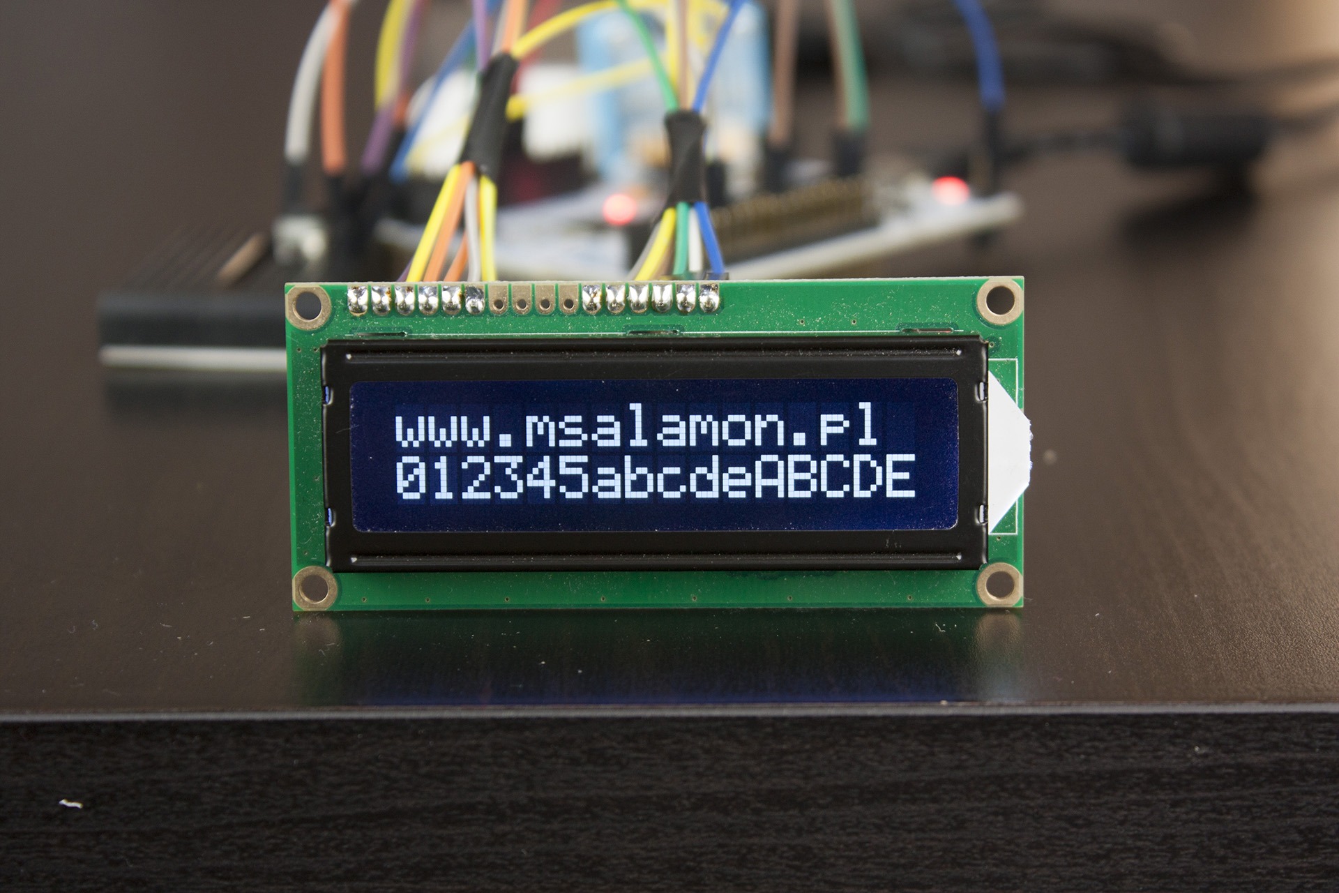
- Black background, white negative text
- White background, black positive text
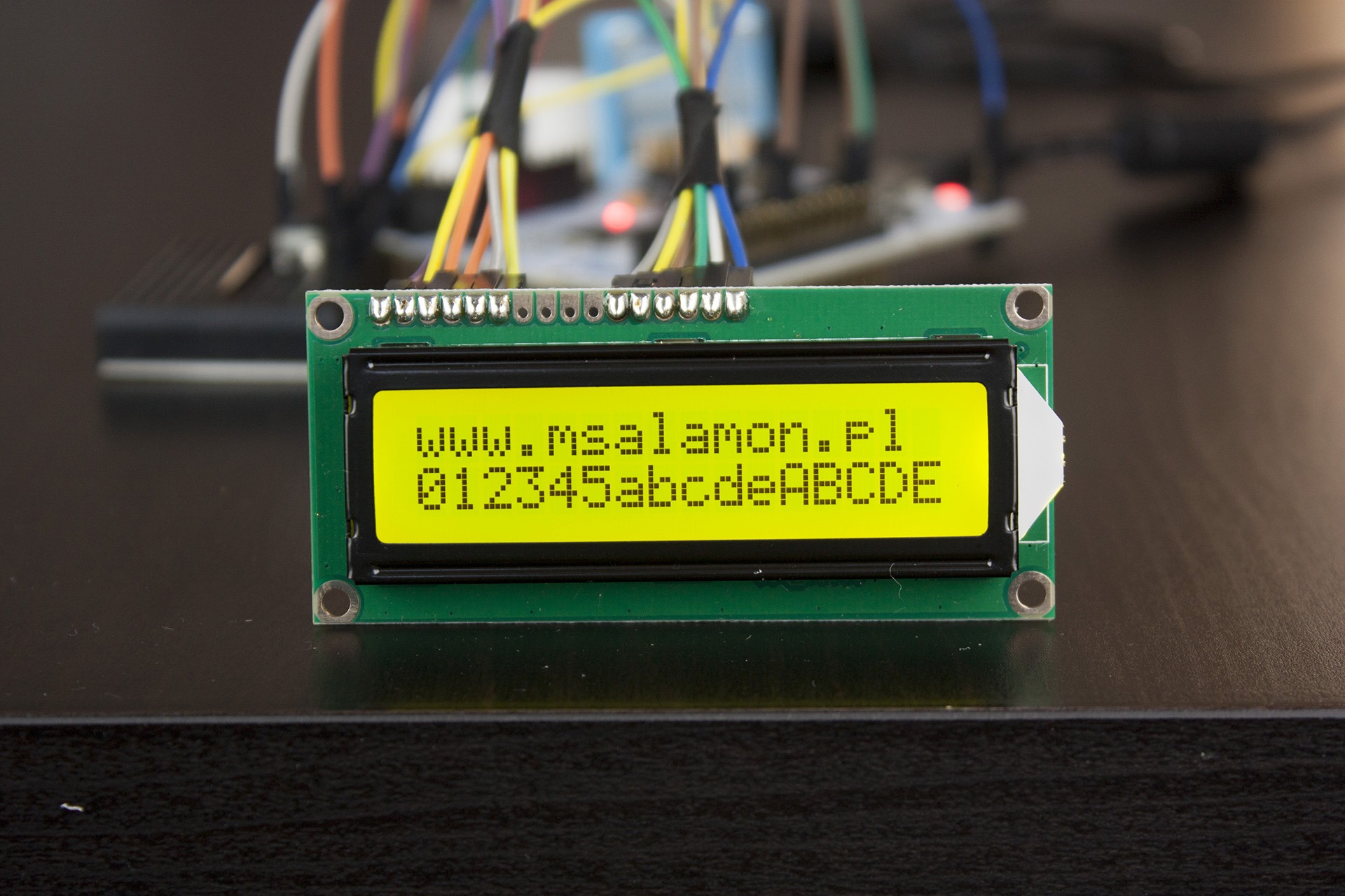
- Green background, black positive text
- There will be two winners. Each of them will get the same set of four displays.
- Prizes will be sent by mail.
- To take part in the contest you must:
- Be a newsletter subscriber: signup link (content in Polish)
- Write under this post what you last made using a display. Remember to enter in the email field of the comment form the same email as the one you used to register for the newsletter.
- End of submissions: 16.10.2018, 20:00
- Selecting the winners:
- Each person may participate with only one comment
- I will pick the 10 most interesting applications from the comments
- I will draw two winners using http://www.losowe.pl/liczba from the range 1–10. Comment numbers will be assigned by date/time added. 1 — oldest, 10 — newest comment
- The draw will take place on Tuesday, 16.10.2018
- The results will be announced in the next post, i.e., 17.10.2018
Below are photos of all the display colors to be won in the contest. Good luck!


0 Comments