Microcontroller projects often need to measure analog signals. Unfortunately, they themselves only understand digital sequences that can take only two states. Most often, these are the ground and supply levels. To measure an analog value, you need to use an analog-to-digital converter — ADC for short. Practically every modern microcontroller is equipped with such a converter. STM32, of course, too.
ADC in STM32
The analog-to-digital converter subsystem in STM32 microcontrollers is fairly extensive. Some MCUs even have two or more such converters. The main features of the built-in ADCs include:
Configurable resolution up to 12 bits
A variety of interrupts, e.g., end of regular conversion, injected conversion, or analog watchdog
Single or continuous conversion mode
Automatic channel scanning
Programmable sampling time
Generating read requests via DMA
These are just the most important items I picked from the documentation. Okay, but how does such a converter work?
Sampling
An analog signal can take various voltage values. Moreover, it is continuous in time. Sampling consists in determining the measurement moments of the analog signal fed to the ADC input. As a result of sampling, we get discrete points that belong to the continuous waveform.
What matters here is the sampling theorem (Kotelnikov–Shannon). It says that to be able to satisfactorily reconstruct the original analog signal from the sampled digital signal, you must sample at a frequency at least twice as high as the highest frequency component of the signal.
In short — when sampling a 1 kHz sine signal, you should do it at least at 2 kHz. A more life-like example — basic audio sampling is done at 44.1 kHz, because it is assumed that the audio signal has a highest frequency component of about 20 kHz.
Quantization
This is the so‑called digital measurement. The sampled quantity is represented as the nearest digital value. Quantization strongly depends on the converter’s resolution. The measured value is expressed as a number of quanta, i.e., the number of the smallest parts into which the full voltage range of the converter can be divided.
With a 12-bit converter, its resolution is 4096 and that’s how many quanta we have. Let’s say the reference voltage, i.e., the one against which we compare our signal, is 3.3 V. A measured value of 4095 corresponds to that voltage. Feeding 1 V to the ADC input, the sample will have the value 1/3.3 * 4095 = 1240.909. As you can see, this value does not fall exactly on an even quantum, so the converter will assign it to 1241. That’s what quantization is about 🙂
The method the converter uses is somewhat different than multiplying voltages like that. The converter does not know the value of the reference voltage. It can, for example, compare the analog signal with a rising staircase signal within the reference voltage range, and then store the number of steps. Remember that after this stage we get a number of quanta, not a voltage value.
Encoding
The last stage is adapting the measured number of quanta to the encoding used in the application. In microcontrollers, this is most often the binary representation of the number of quanta. In the ADC settings, for example, you can align this value to the left or right in the 16-bit ADC output register.
Reading a joystick signal on STM32
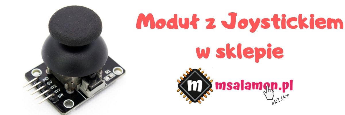
Since you now roughly know how the ADC works, we can move on to using it. The Joystick is nothing more than two potentiometers operating as a resistive divider. The two extreme legs of the potentiometers are connected to + and − supply. The center pin is brought out, and the voltage on it reflects the position of the stick.
Since we have two axes, there are two such potentiometers. As you can guess, we will measure two independent signals. One for the X-axis position, the other for the Y-axis.
Today I’m working on a Nucleo F411RE together with STM32CubeIDE and the HAL F4 libraries version 1.24.1.
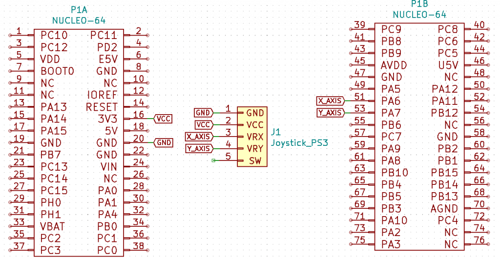
Schematic
I connected the joystick to channels 6 and 7 of the analog-to-digital converter.
ADC readout code – Polling
First I’ll show you the simplest way to read from the ADC, i.e., “manually” triggering ADC conversion and reading the value.
Let’s go to Cube. Create a project for the Nucleo F411RE board. Accept the default configuration of the peripherals on the board. This speeds things up a bit — UART is ready out of the box and HCLK is set to a fairly high value of 84 MHz.
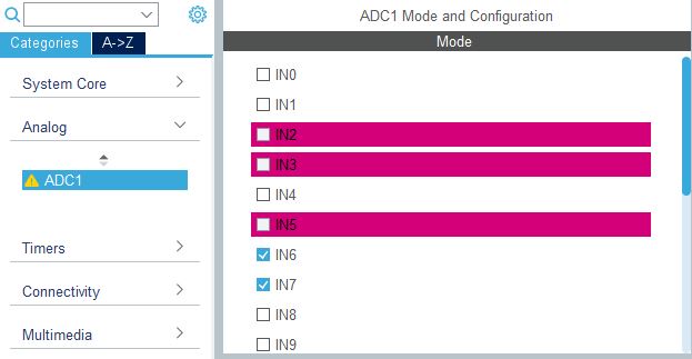
I mentioned I connected to channels IN6 and IN7, so select them in the ADC1 configuration.
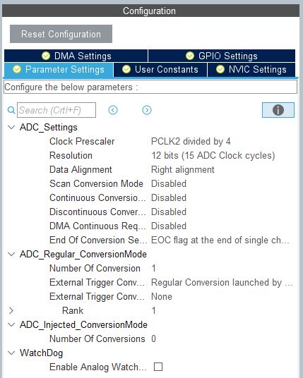
You will notice that the pins on the model next to it light up. Now you can go to the ADC settings. You can set the clock prescaler as you like. I have it set to divide by 4. Make sure you have 12-bit resolution, although of course a lower one will also work correctly. The rest is default as in the screenshot below.
And that’s it for the configuration. You can generate the code and go to the editor.
As I mentioned earlier, polling is “manual” querying of the ADC. In such a case you need to:
Turn on the ADC if needed
Trigger a conversion, i.e., sampling, quantization, and encoding
Wait for the conversion to complete
Read the measured value
The first and second points are handled by the function
To get the next sample, repeat the operation. Alright, alright! I don’t know if you know, but the ADC can convert only one channel at a time. That means it must have specified somewhere which one to handle. By default it’s the first one selected, in our case IN6. To read other channels, before triggering the conversion you need to indicate which channel to use.
I wrote a simple function for this based on the ADC initialization code that Cube generated.
Ultimately, reading two channels and sending them over UART2 looks like this:
/* USER CODE BEGIN 2 */
  HAL_ADC_Start(&hadc1); // You have to start ADC
/* USER CODE END 2 */

/* Infinite loop */
/* USER CODE BEGIN WHILE */
  while (1)
  {
    if(HAL_ADC_PollForConversion(&hadc1, 10) == HAL_OK)
    {
      Joystick[0] = HAL_ADC_GetValue(&hadc1); // Get X value
      ADC_SetActiveChannel(&hadc1, ADC_CHANNEL_7);
      HAL_ADC_Start(&hadc1);
    }

    if(HAL_ADC_PollForConversion(&hadc1, 10) == HAL_OK)
    {
      Joystick[1] = HAL_ADC_GetValue(&hadc1); // Get Y value
      ADC_SetActiveChannel(&hadc1, ADC_CHANNEL_6);
      HAL_ADC_Start(&hadc1);
    }

    sprintf((char*)UartMessage, "X: %d, Y: %d\n\r", Joystick[0], Joystick[1]);
    UART2_Print(UartMessage);
/* USER CODE END WHILE */

/* USER CODE BEGIN 3 */
}
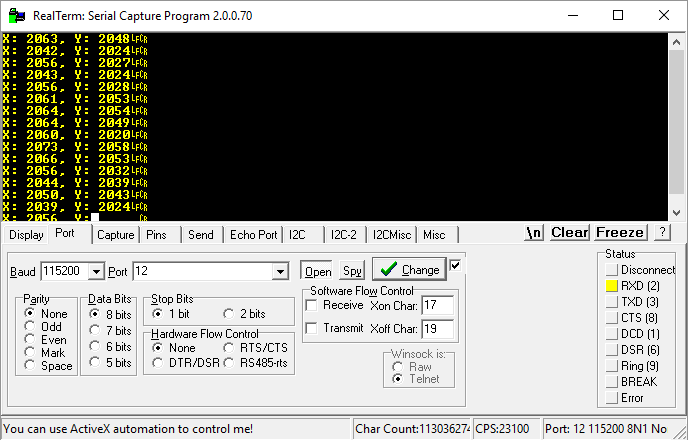
As a result, you get ADC values in the terminal. Without touching the joystick knob, it is in the center position. Half of 12-bit resolution is 2048, so we should expect a value around that.
As you can see, it varies, but it’s always somewhere around 2048. Unfortunately, ADC measurements can fluctuate quite a bit. Many factors affect this, but that’s not today’s topic. You can, for example, collect 10 samples and average them. That will certainly reduce the fluctuations.
I don’t think it’s worth examining the conversion time here. I’ll just mention that its length is affected by factors such as:
Sampling time
ADC clocking
Resolution
Converters can be very fast. In STM32, some reach a maximum sampling of, for example, 5 MSPS (Megasamples per Second) in the STM32F303. External devices can be even faster.
We can’t skip DMA 🙂 Moreover, you can start the ADC once and forget about it completely. Continuous Conversion Mode enables this. It means that the ADC starts the next measurement right after the previous one finishes, without our intervention.
Additionally, if you want to measure more than one channel, Scan Conversion Mode will be useful. Thanks to it, the ADC will switch channels by itself. Nice, isn’t it?
On top of that, let’s add DMA, which will read the measurements on its own and write them to the proper place in memory. No more manual polling and reading!
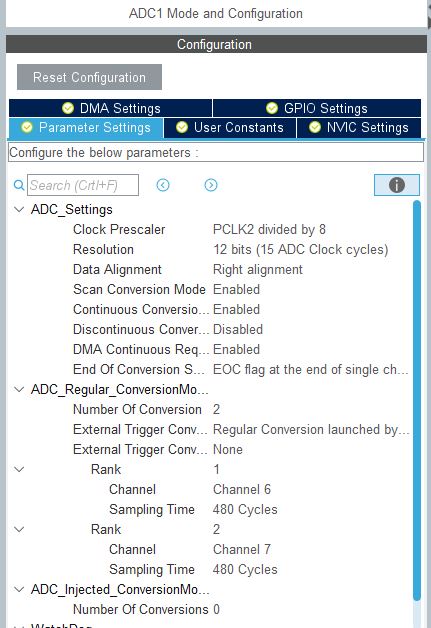
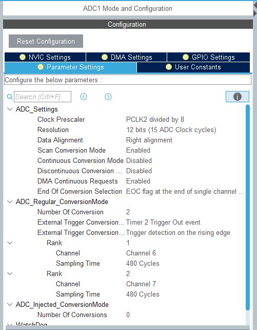
Let’s do it. Let’s configure this magic. Let’s also slightly improve the fluctuations of the readings. Here’s the configuration.
From the top. I increased the ADC prescaler. It will run a bit longer, but it should improve the stability of the reading (longer sampling).
I enabled Scan Conversion Mode and Continuous Conversion Mode for obvious reasons.
I enabled DMA Continuous Requests. Let’s allow the ADC to prod the DMA itself that it has data ready to read.
Make sure that End of Conversion Selection is set to end of single-channel conversion.
Now in the ADC_Regular_ConversionMode set the number of conversions to 2. We want the ADC to automatically scan two channels.
Here I also set the sampling of each channel to the maximum value of 480 clock cycles. This will affect the stability of the readings.
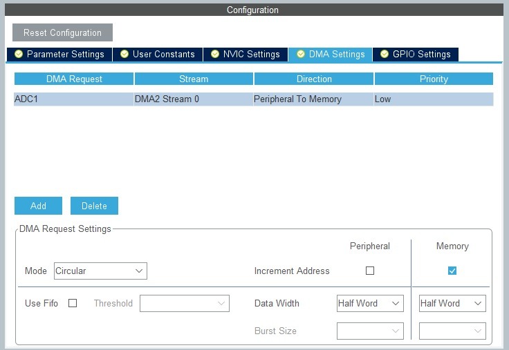
In the DMA Settings tab you also need to set the DMA write to the buffer to be circular.
With this configuration prepared, you can generate the code and move on to code.
We’ve done a lot, but what to put into the code? Well, the entire code that will convert the analog signal and write it to the pre-prepared variables is, attention:
/* USER CODE BEGIN 2 */
  HAL_ADC_Start_DMA(&hadc1, Joystick, 2); // You have to start ADC with DMA
/* USER CODE END 2 */

/* Infinite loop */
/* USER CODE BEGIN WHILE */
while (1)
{

  sprintf((char*)UartMessage, "X: %d, Y: %d\n\r", (int)Joystick[0], (int)Joystick[1]);
  UART2_Print(UartMessage);
/* USER CODE END WHILE */

/* USER CODE BEGIN 3 */
Yes! It’s enough to start the ADC in DMA mode and the readings from both channels will flow into the chosen array (for me uint16_t Joystick[2]). It’s worth mentioning here that they flow at the maximum possible speed.
How fast in this configuration? Let’s check by toggling a test pin on each completed DMA transfer.
Both channels are read every 92 µs, which comes out to about 10.8 kHz. Nothing crazy, but remember that right now we have a very long sampling time.
Alright, but if I wanted to get 44.1 kHz, should I just shorten the sampling and try to hit 44.1 kHz this way? Reduce sampling time — yes, but should you aim blindly so that it’s the full ADC speed? Not necessarily. There’s a better method!
ADC readout code – Timer triggering conversion
You can harness one of the timers to trigger conversion at equal time intervals. Thanks to this, by setting the timer to 44.1 kHz we will be sure that subsequent samples are taken at the right times. Let’s do this!
I’ll leave the conversion time as it was. Let’s try to aim the timer at 200 Hz regular sampling. That will be sufficient for working with the joystick. Such a device does not require frequent reading. Let’s move to Cube. First, the ADC.
As you can see, I disabled Continuous Conversion Mode. This time it won’t be the ADC deciding when to start a conversion.
In the ADC_Regular_ConversionMode section there is a setting called External Trogger Conversion Source. You can choose several timers and the trigger type. It’s either a Capture Compare Event or Out Event. Set Timer 2 Trigger Out Event. It will occur on TIM2 counter overflow.
Now go to the TIM2 settings.
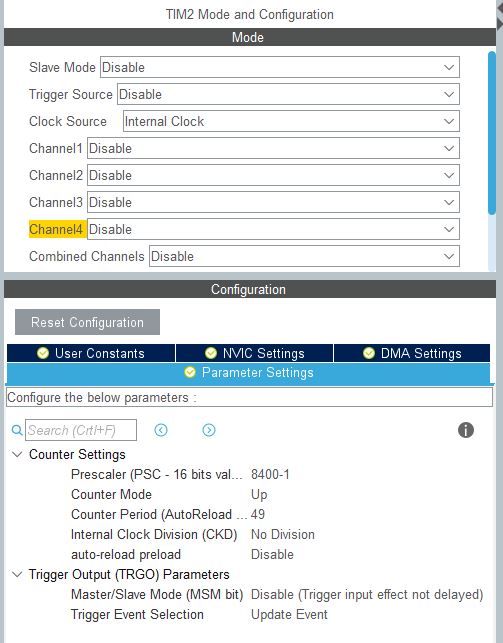
Set Clock Source to Internal Clock. With the clock supplied, now configure the overflow.
We want to get 200 Hz, so each overflow should occur exactly every 5 ms. First set the Prescaler. The “main” frequency is 84 MHz. Dividing by 84, you get a 1 µs tick. Divide further. A division by 8400 gives 0.1 ms. Sounds good, right? Enter 8400-1 or 8399.
Now set the counting period to 49 to get 5 ms per counter overflow.
It’s important to set TRGO, which is the trigger for the ADC. Set Trigger Event Selection to Update Event to pass the appropriate event to the ADC. Now let’s move to the code.
The code is very similar to the one that handles ADC + DMA in continuous mode.
/* USER CODE BEGIN 2 */
  HAL_TIM_Base_Start(&htim2);
  HAL_ADC_Start_DMA(&hadc1, (uint32_t*)Joystick, 2); // You have to start ADC with DMA
/* USER CODE END 2 */

/* Infinite loop */
/* USER CODE BEGIN WHILE */
while (1)
{

  sprintf((char*)UartMessage, "X: %d, Y: %d\n\r", (int)Joystick[0], (int)Joystick[1]);
  UART2_Print(UartMessage);
/* USER CODE END WHILE */

/* USER CODE BEGIN 3 */
}
/* USER CODE END 3 */
The only difference is starting the timer before starting the ADC. Now sampling should happen every 5 ms.
It came out to 4.93 ms, i.e., about 202.8 Hz, so very close. One might wonder why not exactly 5. Setting the overflow to 50, I got 5.03 ms per the analyzer, so a bit better. The question is how accurate my analyzer is. I suspect it’s not high-end equipment 🙂
As you can see, the ADCs built into STM32 have huge capabilities. Their configuration is really extensive, and at the same time simple with Cube. When configured well, using the ADC can come down to just starting it, which is a huge convenience. Arduino doesn’t have this 😉
What do you think about the ADC in STM32? Share your opinion in the comments.
You can find the full project along with the library on my GitHub as usual: link
If you noticed any error, disagree with something, would like to add something important, or simply want to discuss this topic, write a comment. Remember that the discussion should be polite and in accordance with the rules of the Polish language.
Podobne artykuły
No More Multiplexing on GPIO! MAX7219 in Action, Part 2
Measuring Light Intensity Using STM32
Addressable WS2812B LEDs on STM32, Part 3
Darmowy ebook
Dołącz do mojej listy mailowej aby otrzymać darmowy ebook "Pierwsze kroki z STM32".
Udało się!
Potwierdź w emailu dołączenie do mojego newslettera!
In mid-July 2025, together with several leading creators from the embedded industry, we had the opportunity to visit the STMicroelectronics factory in Agrate, Italy. How did it happen? …well, I know 😅 This visit had Read more
UART Communication on STM32. Transmission to PC | STM32 on Registers #6 We have already learned the basic operations on GPIO, as well as ways to delay individual tasks. Today we will go beyond the Read more
Doing 3 Things at Once, or How to Implement a Software Timer? | STM32 on Registers #5 Let’s get to know one of the effective ways not to block the processor’s work by waiting. It Read more
The msalamon.pl blog uses cookies. By using the website, you consent to the use of cookies. More information can be found on the Privacy Policy page. Do not acceptAccept
Privacy Policy & Cookies
Privacy Overview
This website uses cookies to improve your experience while you navigate through the website. Out of these cookies, the cookies that are categorized as necessary are stored on your browser as they are essential for the working of basic functionalities of the website. We also use third-party cookies that help us analyze and understand how you use this website. These cookies will be stored in your browser only with your consent. You also have the option to opt-out of these cookies. But opting out of some of these cookies may have an effect on your browsing experience.





0 Comments