We made it through together how to work with the time and how to tame the date so that the default one doesn’t come back. We’ve also mastered restoring the date from the hardware RTC backup registers after a power loss. However, we do not have backup power, and in this post I’d like to mention it. What’s more, we will switch to an external crystal on the BluePill board, running into a problem… a hardware one.

Battery on VBAT
STM32, unlike for example AVRs, have a special pin for battery power. It’s called VBAT. With its help, the following can be powered:
- External LSE oscillator
- Backup registers
- BDCR register
- RTC
A complete overview of STM32F1 power supply can of course be found in the documentation. Both in the Datasheet and the Reference Manual.
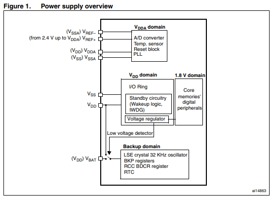
In the diagram you can see something called the Low Voltage Detector. Besides being what the name suggests, its job is to switch the Backup Domain supply exactly when the main VDD supply appears/disappears.
While VDD is present, the RTC and the rest of the crew are powered from the main supply. The moment it disappears, the switch changes the backup area to the supply provided on VBAT.
On VBAT, the backup battery we connect is waiting. Of course, VBAT can also be fed from the main supply instead of a battery, and this is often done. It is even recommended to connect VDD and VBAT externally if we do not use a battery.
I connect a battery to the BluePill
Since my test platform for STM32F1 is the BluePill, I’ll connect a battery to it. I don’t have a CR2032 coin-cell holder, so I assembled myself 2/3 of an AAA battery holder. Two batteries in series give 3 V. In general, for our patient, the battery backup voltage should be 1.8 ÷ 3.6 V, so such a battery set will be perfect.
All you need to do is connect the holder to VBAT and it should work, right? That’s what I thought too… Unfortunately, even though the batteries were connected to the BluePill, the RTC does not keep its settings after disconnecting the USB power cable. Why?
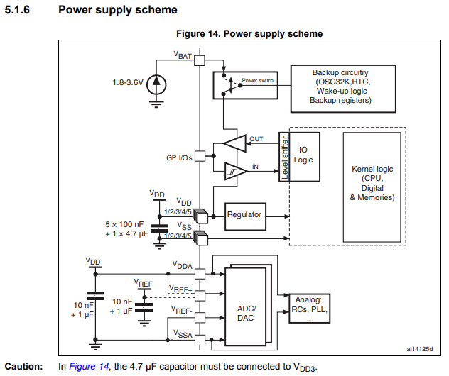
According to the figure above, the battery alone is enough. In reality, it isn’t.
In the documentation titled “Getting started with STM32F10xxx hardware development” you can find the following note.

However, this is not the answer for our configuration. This is exactly how we have it connected, i.e., the battery directly.
We can take a look at the schematic of the BluePill and at the Nucleo. Here is an excerpt from the BluePill.
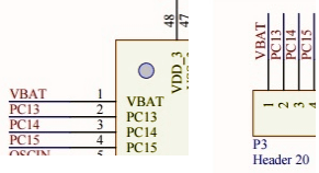
The VBAT pin is routed directly to the pin header. Let’s see how it looks on the Nucleo-64, the most popular size of these boards.
And there is a capacitor (C29). In the documentation they point to this capacitor, but only in the situation where we connect VCC to VBAT. There is no mention of such a one if it’s a battery…
This is a decoupling capacitor for VBAT and VDD. ST placed a 1 uF filtering capacitor and this might be the solution to our problem with the BluePill.
I happen to have 100 nF at hand, not 1 uF, but I think it will be enough. I connect it on the breadboard as close as possible to the VBAT pin and what… IT WORKS!
The RTC also counts on the battery after removing the main power supply. Mystery solved. It’s just a shame that the Chinese didn’t think to add this capacitor…
External RTC crystal
All that’s left is to try switching to an external crystal, which is even mounted on the BluePill board. To do this, it’s enough to enable and switch the crystal in Cube.
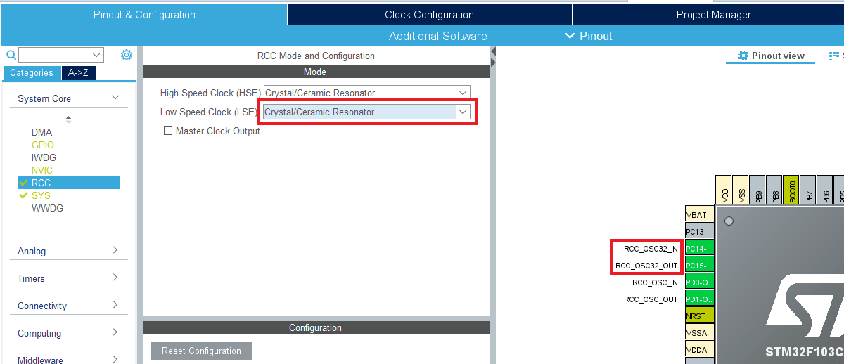
Notice that the oscillator pins on the MCU have appeared as configured. You still need to actually switch the RTC clock to external.
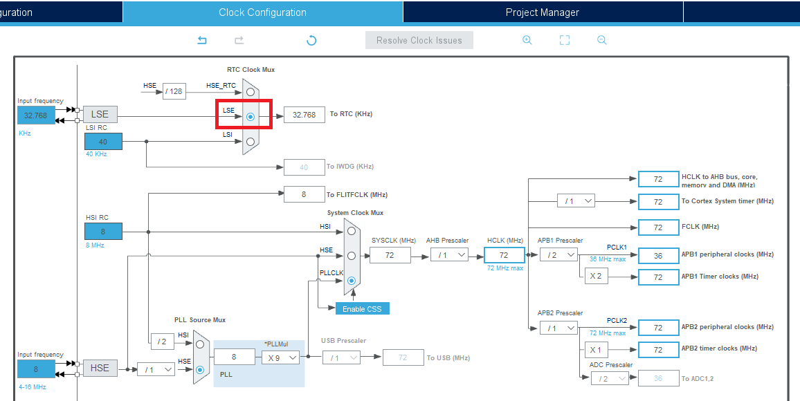
And now the RTC should run on the external clock.
I flash it happily, launch the terminal and what?! The seconds are going about 2 times faster than they should! Scandal!
I dug around the web for a moment about what might be going on and quickly found the cause.
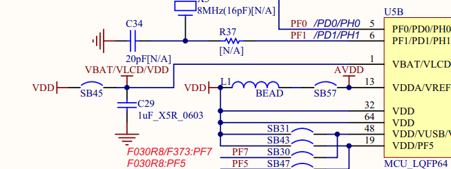
Namely, the excellent Chinese engineers decided they would place an external oscillator for the RTC and connect it to the MCU, but at the same time they routed those same pins to the pin headers in case someone wanted to use them as regular GPIO. The idea sounds nice in principle… until you actually want to use that RTC, not GPIO.
If you still don’t know: oscillators should always be located as close as possible to the MCU pins. This is not without reason. It’s about, among other things, the capacitances between traces.
By adding pin headers, we introduce additional parasitic capacitance, which is not welcome. When plugging into a breadboard, those pin headers and the capacitance associated with them changes even more, as a result of which the resonant frequency of the oscillator/generator shifts.
These parasitic capacitances are on the order of picofarads. However, pay attention to the capacitors that are placed next to oscillators. It’s the same order of magnitude, so such parasitic capacitances from the traces have a truly huge impact on the operation of oscillators.
How to solve this? It would be useful to get rid of these “capacitors” on the pins. Best to simply desolder them. That’s what I did.
The result? A second – by eye – again lasts about a second. We are all saved.

Summary
For the correct use of a battery and an external crystal, a bit of purely electronic knowledge comes in handy. In both cases, capacitances near these elements played a huge role.
Browsing English-language forums, I came across a huge number of threads devoted precisely to these “bugs in STM32” or in the BluePill itself. Unfortunately, things like this most often come with experience…
Luckily you have me and an article like this 🙂 If I helped you, share this post with your friends. I’ll be incredibly grateful!
The full project along with the library can be found, as usual, on my GitHub: LINK
If you noticed an error, disagree with something, would like to add something important, or you simply feel like you’d like to discuss this topic, write a comment. Remember that the discussion should be polite and in accordance with the rules of the Polish language.
Podobne artykuły


0 Comments