I ended the last post about the SSD1327 OLED with the note that in order to use the GFX library, you need to introduce a few modifications to it. Today I’ll deal with those modifications and we’ll have full functionality of our display with a 16-level grayscale. At the end, we’ll check what speeds can be achieved on such an I²C OLED.
Table of contents of the entire series about the SSD1327 OLED:
The library that I pulled from another OLED — the one based on SSD1306 — works with images that use one-bit pixels. In that one, drawing a pixel was written in such a way that if it had the background color (which was passed as an argument), it could even not draw it, creating a transparent background.
And in fact you could use it so that the picture would be drawn in a single color from the 0–15 range, but then why do we need such grayscale? We want to draw nice things, right? Things that will have depth and, for example, will render a nice GUI for us, right?
That’s why we need to slightly modify GFX BW so that it supports images saved in a 4-bit pixel format. Where should we introduce these changes? Exactly — in the image drawing function!
First, we have to find which cell of the image array we want to assign to our buffer. You already know how to do this, because I wrote about it in the previous post. If we go through the image height as j and through the width as i, the cell in the array that interests us is SelectedCell = img[i/2 + j*(w/2)] — w is the image width that we pass as an argument.
As a side note, it would be nice to modify image drawing so that the function itself would read the height and width from the image header that Img2Lcd generates, which I wrote about in this post. Maybe you’ll fork my project on GitHub and write something like that? 🙂
Back to the main topic… having the selected cell, we now need to assign the appropriate pixel value to our pixel in the RAM buffer for the displayed image. In one byte we only have two pixels to choose from. In the previous post we also noticed that even ones are always on the same side of the byte. We need to use that!
The procedure for selecting the appropriate pixel value and writing it into the OLED RAM looks like this.
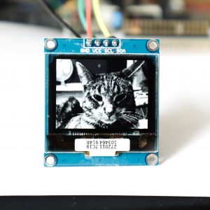
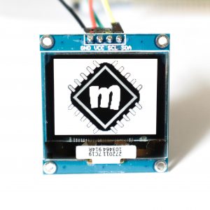
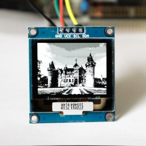
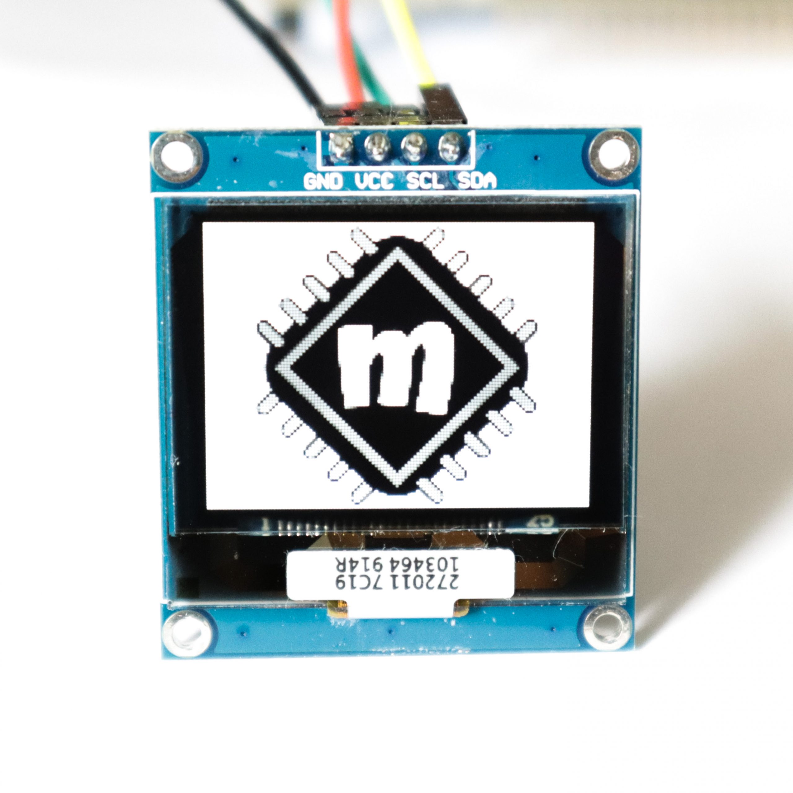
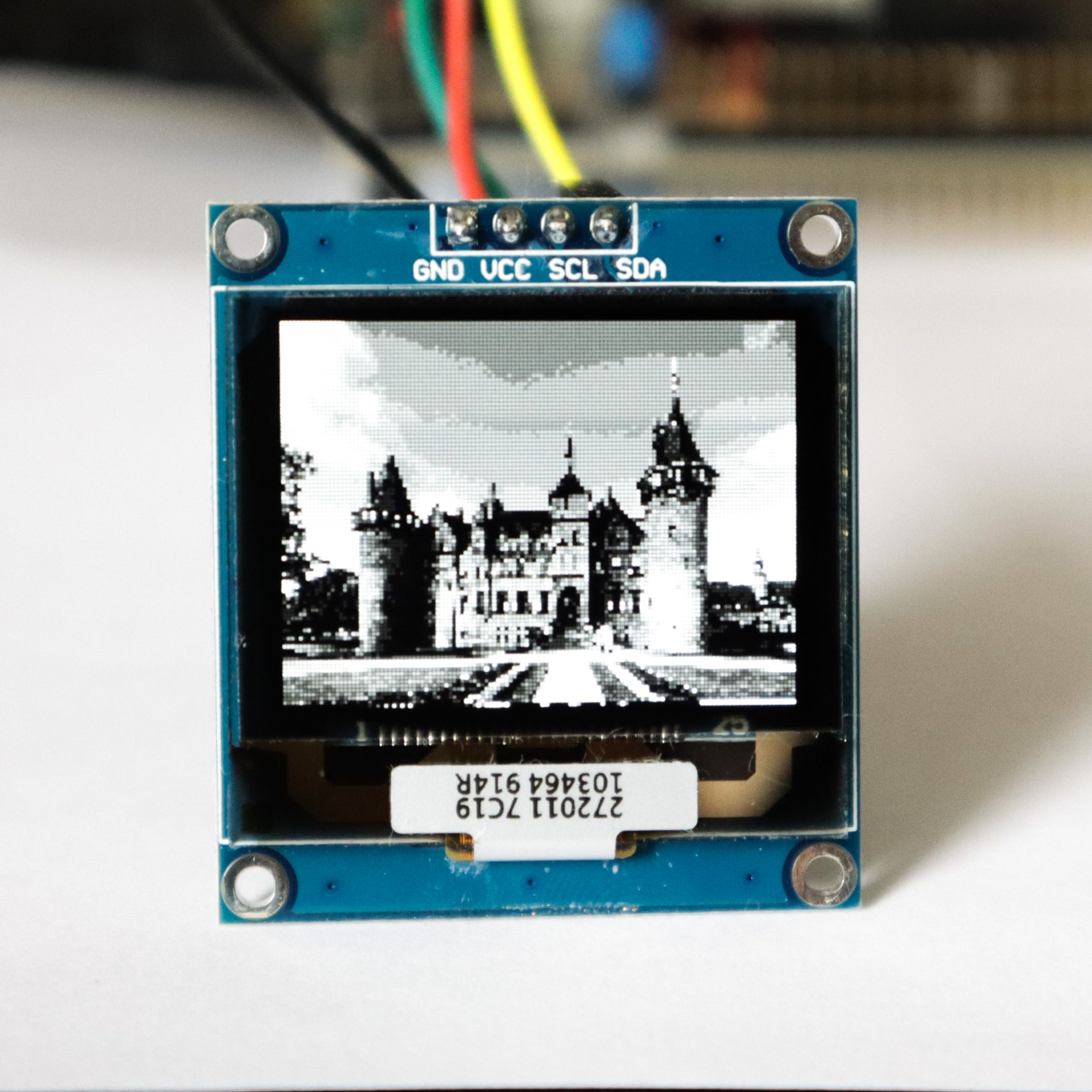
I also made a few minor changes like the library name and so on, so that it matches this display nicely in terms of naming. The result? Beautiful images with color depth 🙂
How fast does it run?
We have much more data here than when sending to a monochrome display. Not only is the resolution slightly higher, but each pixel also contains 4x more data. So can we achieve satisfactory results over I²C? In the first part I did some theoretical calculations. What does it look like in practice? Let’s check!
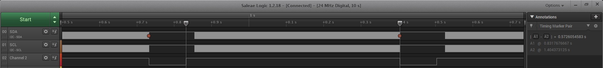
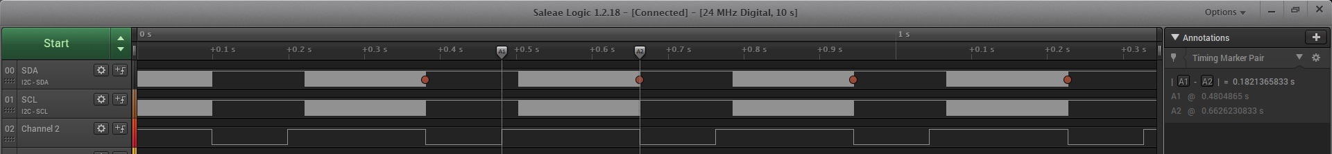
The whole thing at a 100 kHz clock, i.e., copying an image that fills the entire area of the OLED and sending it to the controller, takes as much as 573 ms. An eternity!
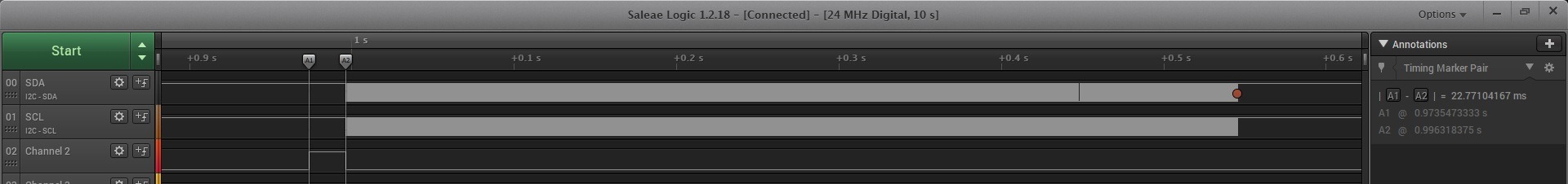
Let’s break it down. Copying the image from the array to the OLED buffer itself is just under 23 ms. Better, but still a lot, right? Remember that this copy uses the DrawPixel function and is not a blind cell-by-cell copy. This introduces some calculations that could probably be partially avoided.
It turns out that sending is insanely long, which you can see in the waveforms. It takes about 550 ms.
Working at 100 kHz I²C means you won’t get more than 2 FPS. Embarrassing! Let’s move to 400 kHz, which is the maximum this OLED can theoretically accept. In theory, it should be 4 times better.
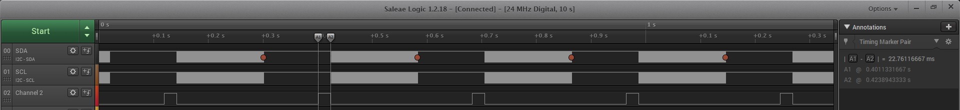
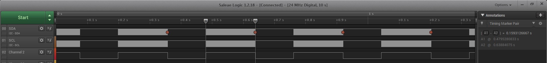
Copying the image + transfer is 182 ms. That would be about 5.5 FPS. Still poor… you’ll see the redraw during full-screen animations.
Copying the image should take the same amount of time, i.e., ~23 ms. Nothing should change in this area.
However, transfer to the OLED is 159 ms.
Acceleration possibilities.
You can try to overclock I²C even more. SSD1327 should easily run at 1 MHz just like the SSD1306. But that goes beyond the documentation, so it’s living on the edge.
A much better solution would be to connect the same OLED via SPI. There you can go up to 10 MHz! That is truly suitable for a fast and unnoticeable image swap.
But… my model doesn’t have SPI on the PCB and doesn’t allow changing the interface with any jumpers. You’d need to look for an OLED version with SPI, and that can be hard to find. Out of ready-made PCB modules, I think only Waveshare has it.
You can make your own PCB! Take the bare OLED module and connect the jumpers appropriately to select SPI. This also involves designing a converter for the panel supply, so it’s rather for more advanced people.
If you stick with I²C, there’s nothing else to do than develop an interface that doesn’t have fast animations. After all, you don’t always need to refresh all pixels, and redrawing the same ones won’t be visible.
Another way could be to give up buffering and draw only in areas that change. With such a controller you can limit the drawing area in the controller, and then simply send pixels. There are quite a few possibilities!
Summary
Reworking the GFX library turned out to be ridiculously simple! Now you can easily throw beautiful images onto the OLED 😉
The speed is worse… Unfortunately, you have to limit yourself to slowly changing content. However, from what I see on the Internet, most projects tend to have slowly changing GUIs anyway 🙂
The full project together with the library can be found as usual on my GitHub:LINK
If you noticed an error, disagree with something, would like to add something important, or simply feel like you’d like to discuss this topic, write a comment. Remember that the discussion should be polite and follow the rules of the Polish language.
Table of contents of the entire series about the SSD1327 OLED:
In mid-July 2025, together with several leading creators from the embedded industry, we had the opportunity to visit the STMicroelectronics factory in Agrate, Italy. How did it happen? …well, I know 😅 This visit had Read more
UART Communication on STM32. Transmission to PC | STM32 on Registers #6 We have already learned the basic operations on GPIO, as well as ways to delay individual tasks. Today we will go beyond the Read more
Doing 3 Things at Once, or How to Implement a Software Timer? | STM32 on Registers #5 Let’s get to know one of the effective ways not to block the processor’s work by waiting. It Read more
The msalamon.pl blog uses cookies. By using the website, you consent to the use of cookies. More information can be found on the Privacy Policy page. Do not acceptAccept
Privacy Policy & Cookies
Privacy Overview
This website uses cookies to improve your experience while you navigate through the website. Out of these cookies, the cookies that are categorized as necessary are stored on your browser as they are essential for the working of basic functionalities of the website. We also use third-party cookies that help us analyze and understand how you use this website. These cookies will be stored in your browser only with your consent. You also have the option to opt-out of these cookies. But opting out of some of these cookies may have an effect on your browsing experience.


 https://sklep.msalamon.pl/


0 Comments