Recently on my social media I pointed out that for quite a long time no article about displays had appeared. In a poll I proposed two models that I have on hand and the winner was an OLED with a controller that enables a 16-step grayscale. Today I’ll start the topic from the theoretical side, maybe even in a light column-like form 🙂
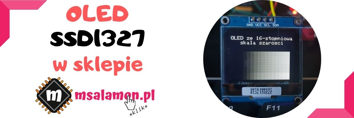
You can buy such an OLED with grayscale from me.
Table of contents of the entire OLED on SSD1327 series:
OLED with grayscale on SSD1327 part 1
OLED with grayscale on SSD1327 part 2
How to prepare an image for an LCD or TFT display?
OLED with grayscale on SSD1327 part 3
OLED displays
These displays have enjoyed tremendous popularity for many years. Maybe not quite as much as the classic 16×2, but still a lot. Their huge advantage is contrast. What is it?
Contrast, in short, is the difference in brightness between the darkest possible point and the brightest. In classic displays with backlight like LCD, TFT, or IPS, this contrast is not that impressive. This is because the backlight in such an LCD works on the entire matrix at once. If you want a black (dark) pixel, you simply block the flow of light from the backlight, which is not always a complete limitation of transmitted light.
An OLED has no backlight. Each of its pixels is a separate diode that emits its own light. What happens when a pixel is supposed to be black? It simply doesn’t light up! Thanks to this, you can get nearly perfect black and it’s quite clearly visible. You can especially see it when you have two screens using different technologies side by side.
A place where you can notice this difference is, for example, any consumer electronics store. OLED TVs on display look insane. I’m already ignoring the fact that they have special demo videos to bring out that contrast even more. It makes the image on such an OLED TV razor-sharp.
In our slightly more hobbyist OLEDs it’s similar. Maybe we won’t get that “razor” because the resolution is too low, but the images displayed by these little guys are pretty enough.
A very important aspect of OLED displays is so-called “burn-in”. Organic diodes have the property that they lose brightness with time spent emitting light. It’s worth checking in the documentation what this time is. Most often, it is given as the time until brightness drops by 50%. This varies depending on the color. Generally it is between 10 and 100 thousand hours.
How to deal with it? Unfortunately, you can’t. However, there’s a certain trick to fool the human eye. Namely, our eyes see RELATIVE differences. That means if you show someone first a display with a brightness of 300 nits and later 400 nits, they won’t be able to tell which was brighter. Even more so if we’re dealing with even higher brightness levels. If you show two such displays side by side—the task immediately becomes simple.
This eyesight “flaw” should be used when designing an application layout. You need, as much as possible, to use all pixels evenly. Then, despite decreasing brightness, differences between pixels won’t be visible, and in fact we’ll get the illusion of no burn-in.
Hence various hardware graphics helpers appear in OLED controllers for example for scrolling 🙂 Such shifting of pixels can be set as a screensaver.
Grayscale
Right. Simple OLEDs like those with the SSD1306 driver can display only 2 colors: black and the pixel color (white, blue, yellow, etc.). You can adjust their brightness, but this adjustment is applied to the entire pixel matrix. Because of this, to show shadows in images you need to use weird graphic tricks and “dithering”.
Enter the SSD1327 controller on a big white OLED-pixel horse. It’s worth taking a look at its documentation, which I’ll deal with now.
The grayscale supported by this controller is nothing more than controlling pixel brightness, but not for the whole matrix—rather, for each point individually.
SSD1327
When describing this controller I will refer to the well-known SSD1306 from the most popular OLEDs.
Right from the start, this controller can handle larger matrices. Up to 128×128 pixels. In the SSD1306 it was max 128×64 px. That’s a matrix twice as large. Even the test display has a slightly higher resolution: 128×96 px.
The RAM that stores the currently displayed image is 128x128x4 bits. Ohoho what are those magical 4 bits?
It is nothing other than the pixel color. It is 4-bit, so we immediately have the information that each pixel can take 16 of these colors. These colors are nothing other than the grayscale levels.
Interestingly, 4 bits have their own name in computer terminology! I recently made such a riddle on Facebook and Instagram. It turns out you know this name. These 4 bits are professionally called a nibble in English. In Polish it is “tetrada”. However, I think “half-byte”, as some people suggested, will also be an appropriate word. Kudos to everyone who answered correctly 🙂
Alright, since one pixel = 4 bits, is the RAM chopped up for 4-bit access? NO! It’s classic RAM with 8-bit (byte) access. Simply one cell holds information about two neighboring pixels. You can see this in the RAM diagram.
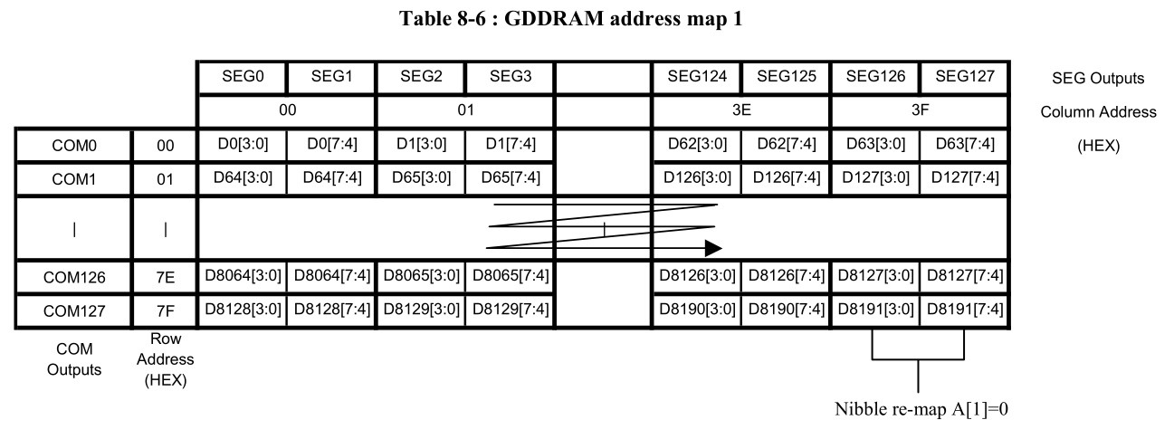
Sounds nice, because the data is packed, which means a bit less transmission for each pixel. There’s only one trap! How to change the color of one pixel while not touching the other one in the byte? You first need to read the selected byte from the display RAM, replace the correct pixel, and send the whole byte back. This adds quite a bit of work if we don’t buffer the whole frame in the microcontroller’s memory.
As you can quickly calculate, to buffer a 128×96 pixel display you need 128*96*4 bits = 4096 bytes of RAM. That’s not much for an STM32. It should be doable.
If, however, you would like not to use buffering, then you need to read data from the display RAM. The SSD1327 controller can work with several interfaces. Most commonly in circulation we can find ready-made PCB modules with I²C brought out. However, I once worked with this controller using SPI and there is a small trap here. With SPI there is no possibility to read data from the OLED controller. Then only buffering in the MCU RAM comes into play, or using the display in such a way that you don’t write individual pixels.
Among other differences compared to the SSD1306 you can notice that SSD1327 requires an external supply for the matrix. It does not have an internal charge pump, so you need to provide 8÷18 V to the appropriate pins. Interestingly, this supply affects brightness, so it also affects pixel burn-in. The external supply is handled on the OLED PCB via a simple converter.
Interface speeds
I will check specific speed values and timings as well as frames per second in the next posts once I have the library. However, I can try to calculate how it will look in theory.
The display from my shop has only an I²C interface brought out. The documentation says the clock on it can be up to 400 kHz. Not amazing, but better than 100 kHz. I bet it can be overclocked easily.
Ignoring the times for preparing data and setting the pointer in the display RAM, using DMA to send it is 4096 bytes. With a 400 kHz clock, one byte is sent in 20 µs. So the whole frame will transfer in about 82 ms. A bit long, right?
Sending full frames in a loop without restraint will give a bit over 12 Hz. A bit too little for smooth animation playback. I²C is poorly suited for that.
What about SPI? The clock allows communication at 10 MHz. That’s a much nicer frequency. 100 ns per bit, 800 ns per byte, so per frame it comes to 3.2 ms. That gives about 312 Hz, so the headroom for smooth animation at 25÷30 Hz is huge.
It would be better to have SPI available for fast changes, but you can still show a lot on I²C. I’ll show you that in the next article!
Summary
I did a bit of theorizing about our hero. In the next posts I’ll show the code and operation of this display. Shortly after writing this post I already ran the first version of a working library.
If you liked the article, you can support me by buying something from me 🙂 https://sklep.msalamon.pl/
If you noticed an error, disagree with something, would like to add something important, or simply feel like discussing this topic, write a comment. Remember that the discussion should be polite and in accordance with the rules of the Polish language.
Table of contents of the entire OLED on SSD1327 series:
OLED with grayscale on SSD1327 part 1
OLED with grayscale on SSD1327 part 2
How to prepare an image for an LCD or TFT display?
OLED with grayscale on SSD1327 part 3
Contest results
Time for the long-awaited contest results! Jeeez, choosing as always is difficult and I have the impression that I’m being unfair to the others who didn’t win 🙁 I like all the ideas and I will definitely implement them!
But someone has to win. Here are the three winning comments:
1. Radee
AES128 communication encryption
Great topic! I forgot that STMs have hardware RNG modules. Additionally, there is ST’s crypto library, so we can test it.
2. Micro
I would really like to see an article about using external memory, e.g. FLASH / RAM, with the help of e.g. quad / dual SPI; it can be an interesting topic because sometimes you may run out of space for the program and data in cache, and besides that maybe something about built-in serial interfaces for displays, e.g. LCD parallel interface, 8080/6800 modes; I think most microcontrollers, or at least I know F4 and H7, have such things and an interesting possibility is using hardware communication inside the microcontroller itself, because if it’s there why not use it. Those are my ideas, maybe something will catch on? I’m a beginner myself and I don’t know much about them, which is why I think others might also be curious to learn something about it.
Maybe it’s already a bit too late, but could you do something about the interface (8- to 14-bit parallel camera interface) that can be found in stm32f4 (in my case stm32f446re) and stm32H7 (in my case stm32H745zi) using e.g. an OV7670 camera (8-bit). I know there are a few examples using it on arduino in software, but I don’t know if there are any for stm32 using that interface.
Hardware support for TFT or a camera is great. This is something Arduino doesn’t have, and it’s worth learning! It would be useful to have some Discovery boards in the shop along the way 🙂
3. Marcin Wk
Mareusz! IoT is increasingly boldly entering everyday life. Therefore this is a serious argument to make a post or even a series of posts about Ethernet and STM32? True, IoT is rather associated with WiFi, so here’s my second argument: I saw many Nucleo-144 boards with an Ethernet port, also in your shop, and there’s little information about this interface on the internet, time to change that? Currently I’m building/programming automation for my future house, which I hope to move into by the end of the year. A controller based on STM32F4 and connectivity to the world using the well-known enc28j60. On nucleo 64 I’m already starting to run out of gpio, so I’m thinking about nucleo144 and using the built-in ethernet?
I’m curious why so few people describe their battles with Ethernet on STM32. I’ll have to check it out! Both the external ones like W5500 and the ones built into Nucleo-144.
Congratulations to everyone for the great ideas!
I ask the winners to contact me, preferably by email: mateusz@msalamon.pl to arrange shipping of the prizes.
Next year I hope I’ll manage to prepare really solid prizes 😉
Podobne artykuły




0 Comments