The topic of nRF24L01+ had been sitting on my “to-do” list basically since this blog was created. This chip is one of the most popular radio ICs. Modules from China cost proverbial pennies, and the capabilities offered by these nRFs are out of this world. So why did it take me so long?
The problem was that a few years ago, when I was still coding only on AVR, I had a huge problem with these modules. I couldn’t get them to work with interrupts. Now, with much more experience, it worked almost right away. Once I got unstuck, I decided to strike while the iron was hot and write this mini-series about these great modules.
The entire series about nRF24L01+:
nRF24L01+ chip
This chip supports radio communication at 2.4 GHz. It has 126 programmable channels on which it can transmit. The best part is that these channels do not overlap like, for example, WiFi channels.
You can also set the data rate and transmitter power. This is useful for reducing power consumption. Power Down mode is also useful for that.
Now the best part. The nRF24L01+ chips support the Enchanced ShockBurst™ technology. Sounds like some weird advertising slogan. What does it give us? The most important things are:
- Automatic handling of radio packets. You don’t have to think about whether you need to send start bits, stop bits, preambles, and other such things over the air. You only load into the nRF what you actually want to send, and it wraps it into packets by itself. On reception, it will also decode it by itself, returning your data, i.e. the so-called payload.
- The payload is dynamic. What does that mean? You can transmit messages of size 1–32 bytes, and the modules will tell each other how much data came through in the payload.
- Automatic acknowledgment of packet reception. You don’t need to send any “okays” back. The ACK is hardware-based and if you received the payload, both sides will know about it.
- Automatic CRC checking. You don’t have to calculate and verify it yourself. The chip does it for you! If a packet arrives corrupted, the nRF will reject it and won’t send an acknowledgment, for example forcing retransmission by the transmitting chip.
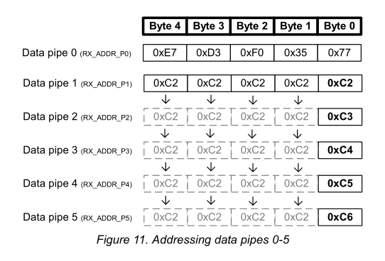
- Reception from multiple transmitters. Up to six. This helps connect chips in a mesh, star, and other topologies.
The chips are addressed with 3–5 bytes. The “tunnel” address of Pipe 0 and 1 is basically arbitrary. The remaining Pipes 2–5 have the same most significant part of the address as Pipe 1. They differ only in the least significant byte. This is explained by this figure from the documentation.
Modules with nRF24L01+
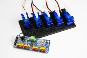
I mentioned at the beginning that the chip’s popularity is due, among other things, to cheap and easily available modules from China. The basic module has pins on classic 2.54″ headers and costs a few złoty.
There is also a “MINI” version that is slightly smaller and allows SMD mounting.
Those who care about good range will like modules with a large external antenna and an RF amplifier. You can get pretty good ranges with these modules.
You can buy all these modules in my shop.
Unfortunately, it’s not all that beautiful. I need to warn you a bit. In China, as China goes, copying is popular. The nRF24L01+ chip was copied and released under the name Si24R1. They work “the same,” but you know how that can be. I’d approach them with a bit of distance.
In my shop I clearly mark which chip is placed on the module. But you know—anything can be written on an IC, so in reality nobody knows what’s inside. On my side, I do what I can.
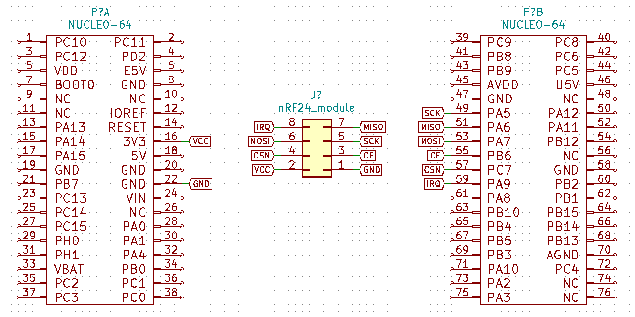
Wiring diagram to Nucleo
I’ll use the classic 2.54″ pin modules. The wiring for the transmitter and receiver is identical. Below you have the pinout of the module itself. Unfortunately it is not labeled on the PCB, so wiring takes a moment.
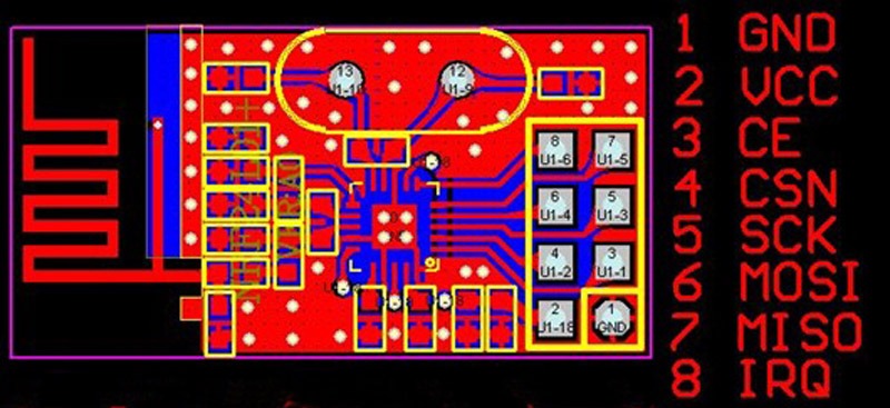
What’s important is that the nRF24L01+ chip is powered from 3V3. If for some reason it doesn’t want to work properly, it’s worth adding an electrolytic capacitor as close as possible to the power pins, e.g. 1 uF. It can help a lot.
Configuration in CubeIDE
For tests I used two almost identical Nucleo boards – F401RE and F410RB. Thanks to this, the transmitter and receiver projects are almost the same 🙂

Software versions I use:
- STM32CubeIDE v1.3.0
- STM32CubeMX v5.6.0 built into the IDE
- HAL library for F4 v1.25.0
I created the project with the default peripheral settings for Nucleo – UART and Serial Debug are already taken care of 🙂
To communicate with the microcontroller, the module requires an SPI interface. It supports up to 10 MHz, so standard as befits SPI chips. You can probably overclock it if you really want 🙂
I like using Arduino pins because I have easy access to them with a logic analyzer as well. SPI1 is on those pins, so that’s what I’ll use.
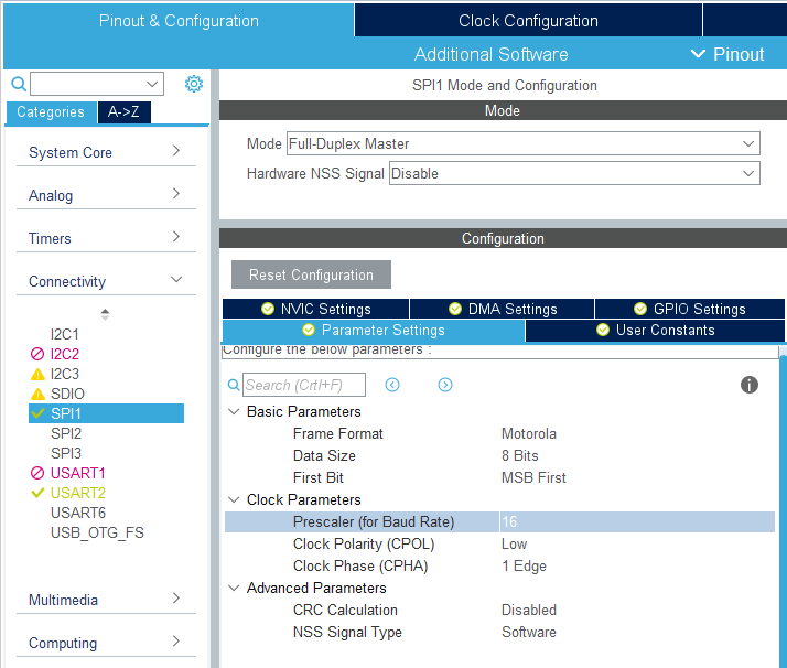
Set it to Full-Duplex Master mode. If you did it like I did with the default settings, then HCLK is set to 84 MHz, and therefore SPI is clocked with 42 MHz. I set the SPI prescaler to 16, so effectively on the SPI clock I’ll get around 2.63 MHz. Perfect for viewing on a low-performance logic analyzer.
My configuration is in the screenshot.
The nRF24 modules also have a few other pins: CE, CSN, IRQ. The first two are inputs, so you need to set the MCU pins as GPIO Output.
IRQ is an interrupt, so set GPIO_EXTI.
I used PA9, PB6, and PC7, which are next to the SPI pins. Everything is close together.

For now we won’t use interrupts, but it’s worth having the GPIO already configured 🙂
Code
As I mentioned at the beginning of this post, I had the library partially prepared from a few years ago. From what I recall, I based it on the popular and fairly well-working RF24 library from Arduino. Back then it didn’t have good interrupt support, and my attempts ended in a temporary failure.
I’m coming back stronger and I’ve already got working interrupts, but those will be in the next part of the nRF24 series. Today I’ll show you the chip configuration and the basic mode of operation, i.e. polling.
I’ll start with initialization.
void nRF24_Init(SPI_HandleTypeDef *hspi)
{
	hspi_nrf = hspi;

	NRF24_CE_LOW;
	NRF24_CSN_HIGH;

	nRF24_Delay(5); // Wait for radio power up

	nRF24_SetPALevel(NRF24_PA_PWR_0dBM); // Radio power
	nRF24_SetDataRate(NRF24_RF_DR_250KBPS); // Data Rate
	nRF24_EnableCRC(1); // Enable CRC
	nRF24_SetCRCLength(NRF24_CRC_WIDTH_1B); // CRC Length 1 byte
	nRF24_SetRetries(0x04, 0x07); // 1000us, 7 times
	nRF24_WriteRegister(NRF24_DYNPD, 0); // Disable dynamic payloads for all pipes
	nRF24_SetRFChannel(10); // Set RF channel for transmission
	nRF24_SetPayloadSize(0, NRF24_PAYLOAD_SIZE); // Set 32 bytes payload for pipe 0
	nRF24_EnablePipe(0, 1); // Enable pipe 0
	nRF24_AutoACK(0, 1); // Enable auto ACK for pipe 0
	nRF24_SetAddressWidth(NRF24_ADDR_SIZE); // Set address size

	nRF24_Delay(20);

	nRF24_EnableRXDataReadyIRQ(0);
	nRF24_EnableTXDataSentIRQ(0);
	nRF24_EnableMaxRetransmitIRQ(0);

	nRF24_Delay(20);

	nRF24_ClearInterrupts();
}
As usual in my libraries, you need to provide a pointer to the SPI handler you want to use.
You may have noticed earlier, but we have a pin called CE. This is not the SPI CS pin. This pin is used to select transmit and receive modes. The library handles it fully 🙂
Initialization includes, among other things:
- Setting transmitter power
- Setting data rate
- Enabling CRC and retransmissions
- Setting the RF channel
- Payload size
- Address size
At the end there are interrupt settings. For now I disabled them all, but you still need to clear them. Only the reflection on the IRQ pin will be disabled. The registers behave as if those interrupts existed, and we will use them to find out whether something arrived.
All these settings, especially transmit power, speed, and channel, you can freely set according to your preferences. Whether you change it in initialization or later—that’s up to you.
There are also two constants that you set in the nRF24_Defs.h file.
#define NRF24_PAYLOAD_SIZE 1

#define NRF24_ADDR_SIZE	3
They correspond to the payload size (1–32) and the addressing length (3–5).
Now you need to set addresses. In RX you set the address at which you want to receive. In TX – which one you transmit to. Finally, I enable the appropriate mode.
For the transmitter it will look like this.
  nRF24_SetRXAddress(0, "Tx");
  nRF24_SetTXAddress("Rx");
  nRF24_TX_Mode();
Receiver:
  nRF24_SetRXAddress(0, "Rx");
  nRF24_SetTXAddress("Tx");
  nRF24_RX_Mode();
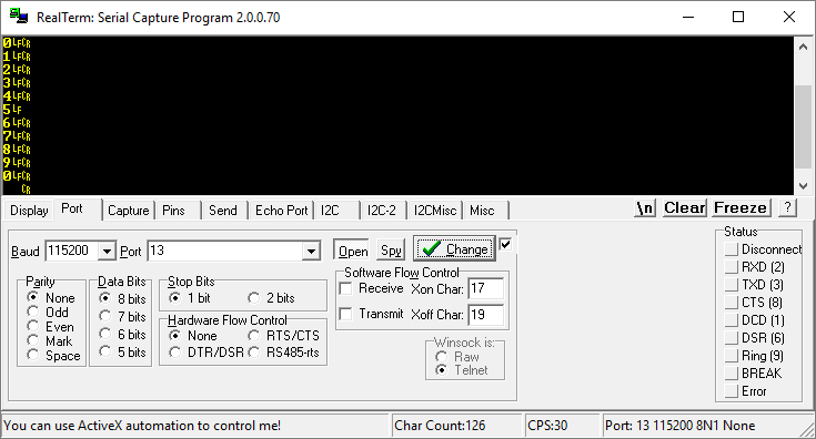
And now you can transmit/receive. In the example I have the payload length set to one character, so I’ll transmit digits 0–9.
	  for(i=0; i<10; i++)
	  {
		  MessageLength = sprintf(Message, "%d", i );
		  nRF24_WriteTXPayload(Message);
		  HAL_Delay(1);
		  nRF24_WaitTX();
		  HAL_Delay(1000);
	  }
In this simple code I prepare a number as an ASCII character, write it to the TX payload, and wait for transmission. And so every second. How to receive it?
	  if(nRF24_RXAvailible())
	  {
		  nRF24_ReadRXPaylaod(Nrf24_Message);
		  MessageLength = sprintf(Message, "%c\n\r", Nrf24_Message[0]);
		  HAL_UART_Transmit(&huart2, Message, MessageLength, 1000);
	  }
The nRF24_RXAvailible() function checks the RX_DR bit in the status register. It tells us that something arrived and is waiting in the FIFO of the nRF. If we have something, we need to read it with nRF24_ReadRXPaylaod().
Later I restore the number and push it to UART. Result.
Summary
This is what the simplest handling looks like, i.e. blocking polling. I also haven’t used dynamic payload yet. The nRF24L01+ chip can tell us how much data arrived and how much data is to be sent. Then we don’t have to limit ourselves to a fixed message length. It will definitely be useful.
I’ll deal with that in the next post. Same with interrupt-based handling, which is definitely better than polling the chip.
If you liked the article, you can support me by buying something from me 🙂 https://sklep.msalamon.pl/
The entire series:
You can find the full project with the library, as usual, on my GitHub: TRANSMITTER, RECEIVER
If you noticed a mistake, disagree with something, would like to add something important, or simply feel like discussing this topic, write a comment. Remember that the discussion should be polite and follow the rules of the Polish language.
Podobne artykuły


0 Comments