Anyone who has spent even a moment dealing with robotics knows that distance measurement plays an incredibly important role in this field. Practically everywhere we deal with devices that move, some kind of obstacle detection is advisable. This is often implemented by measuring distance.
Such measurement can be done in many ways. The methods differ in operating speed, accuracy, and the maximum measurable distance that can be achieved.
Among these solutions, ultrasonic sensors are incredibly popular. For just a few zlotys you can buy an HC-SR04, which performs perfectly not only in hobby electronics. One of its drawbacks is size. It won’t be suitable for a small robot, and it’s also hard to hide.
Small laser sensors come to the rescue. Today I took a closer look at an ST sensor labeled VL53L0X.
You can find the second part with interrupt handling here
Micro ToF sensor VL53L0X
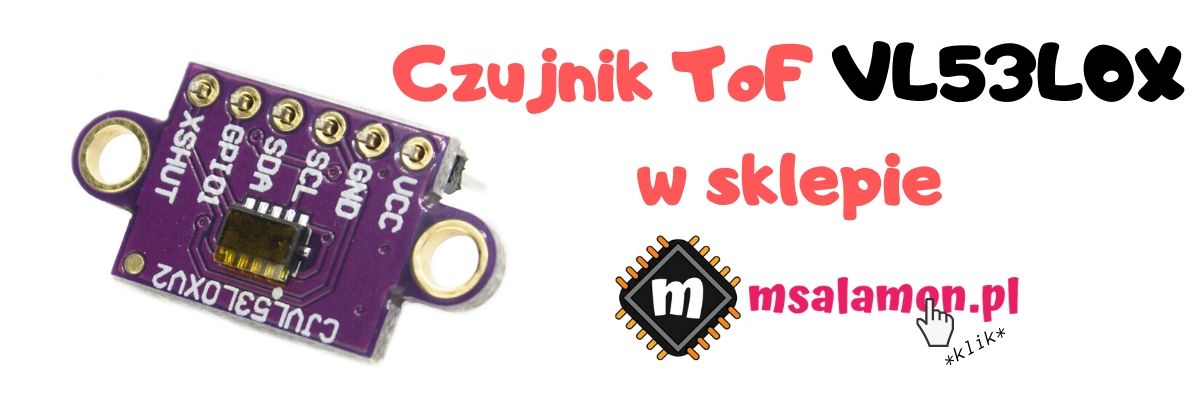
This is a ToF (Time-of-Flight) sensor, meaning that distance is measured by timing the flight of, in this case, a laser beam. The sensor checks how long it takes for light to reach the object, bounce off it, and return to the receiving sensor. Ultrasonic sensors work in a similar way.
ST boasts that this is the smallest laser sensor in the world, and the dimensions are indeed impressive. The whole little chip measures only 4.4 x 2.4 x 1 mm, so it’s just slightly larger than a resistor in a 1206 package.
The laser used in the sensor, with a wavelength of 940 nm, is designed to meet standards for use around the “naked” eye. Being around it should not pose any risk.
Interestingly, such lasers are sometimes used to aid autofocus in digital cameras. Some older smartphones boasted laser autofocus—I even had one. Now I don’t recall any newer handsets having a laser. Maybe it wasn’t that great.
The sensor communicates with the host via the I²C interface. In addition to the standard bus pins, there’s also an interrupt output and an input for turning the sensor off.
ST includes a complete library with the sensor, which they proudly call an API. It contains probably everything you can do with the chip. This is quite a good move, because the chip is very complex for a simple sensor. It contains dozens of registers you can talk to. For beginners, this can cause quite a headache.
However, simply using the library can also lead to a migraine. The library is written in a generic way, so it takes up a lot of code. It’s no secret that lots of code means lots of Flash memory. I’ll check how much it actually is.
Additionally, it’s very hard to find sensible descriptions of how to use this sensor. You have to dig through the inhumanly written API documentation and examples for Nucleo boards and shields with these sensors.
The Getting Started guides I mostly found boil down to taking the same Nucleo as in the examples, flashing a prebuilt binary, and enjoying the results. No no no, ST…
Enough of my whining. Let’s move on to how to run this bulky API on any microcontroller.
What do you need?
You will of course need a microcontroller. Specifically, an STM32. Today I took the STM32F401CCU6 from the new items in my store. I wrote more broadly about these boards in one of the previous articles.
As development tools, I used STM32CubeIDE version 1.1.0, which has the integrated STM32CubeMX 5.4.0. The HAL libraries I use are F4 v1.24.2.
Besides the board and the IDE, you also need the aforementioned API. You can find it here.
And finally, a package with an add-on for Cube for the Nucleo shield with our sensor will come in handy. I’ll explain in a moment why both the API and the Cube extension are needed.
Project in Cube
Choose the F401CEU6 CPU, unless you have a different one. First, the clock. For tests I like to use the highest possible frequencies. I set 84 MHz HCLK using the external 25 MHz crystal found on the board. To use it, in the RCC tab you need to select High Speed Clock (HSE) as Crystal/Ceramic Resonator. Then in Clock Configuration from the top menu, enter the number 84 in the HCLK field and press Enter. Cube will calculate everything for you 🙂
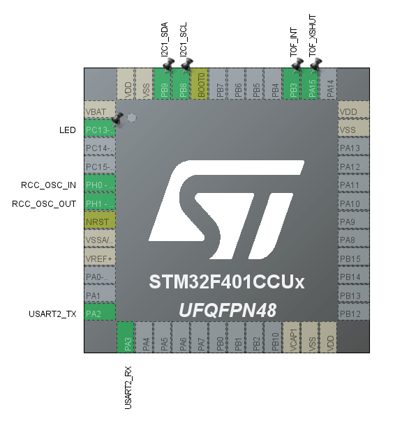
For communication you’ll need I²C, so configure one of the available interfaces. I chose I2C1 on pins PB8 and PB9. The sensor supports 400 kHz, and you should stick to that. For comparison, leave me 100 kHz 🙂
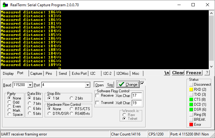
I will send the measurement results via UART. Initially I wanted to use USB, but that’s a bit more hassle. I’ll cover USB another time 🙂 I took USART2 as usual, like on every Nucleo, and connected to the PC through a converter. I set it to 115200 8n1. No surprises.
Remember that the ToF sensor has two more pins — the interrupt called GPIO1 on the board and XSHUT for turning the sensor off. I connected both to the microcontroller. While I will definitely use the interrupt, XSHUT may not be needed right now.
When would XSHUT be needed? The first thing that comes to mind is saving energy. That’s true, but another situation where you can use it is connecting multiple sensors to one bus. Unfortunately, VL53L0X sensors don’t have a configurable I²C address, so you have to get creative this way. XSHUT allows switching between sensors without reinitializing them.
This is how the “schematic” from Cube looks.
Launching the VL53L0X API
I won’t hide that it was hard for me to find on ST’s pages how to use the API. Texts pointing to documentation describing the use of the API led to a pointless 2-page document that only showed the API directory structure. Who needs that? In the end I pieced together several different tips from the Internet, read some of the massive documentation, and it worked 🙂 Here’s what I did.
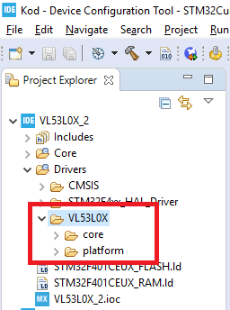
Unpack the packages with the API and the Nucleo add-on. The first thing to do is copy the API into your project. It’s the entire contents of ..\VL53L0X_1.0.2\Api\
I put it into the Drivers directory in the project.
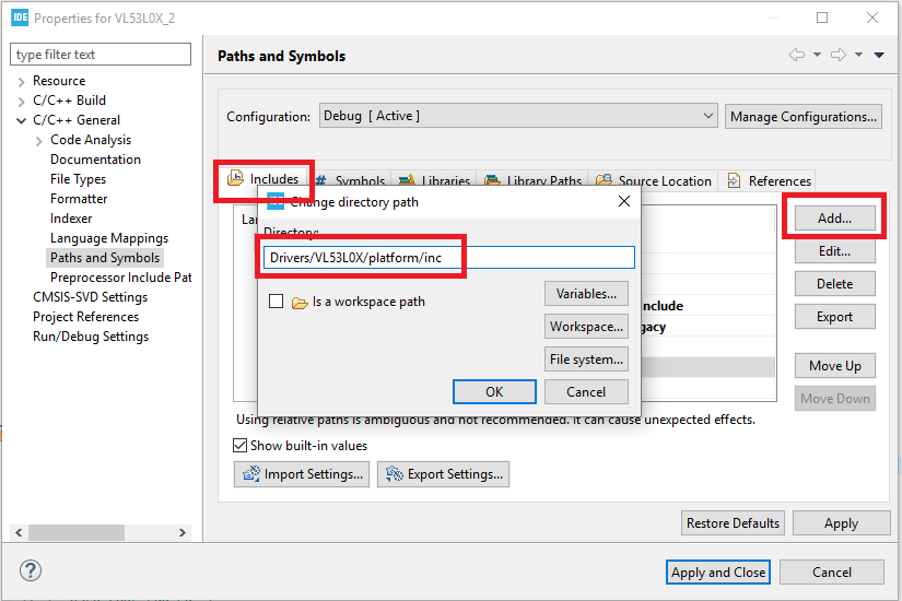
Now you need to add the header and source file paths to the project. Do this by going to Project > Properties > C/C++ General > Paths and Symbols. In the Includes tab, add the inc folders from the API, and in the Source Location tab, add the src folders


The header you need to include in main.c is vl53l0x_api.c. Unfortunately, attempting to compile with the API added will throw a few errors.The compiler tells us it’s missing the file… windows.h?! It turns out that within the API there are files corresponding to the platform on which we want to use it. When downloading the API from ST’s website, it’s configured by default to work on Windows and includes such examples. In my opinion this is a bit strange, but OK. We need to make sure that the platform is configured as our microcontroller.
For this we will use the Cube extension package for our sensor. As it happens, it’s written using HAL, so no matter which Nucleo the examples were written for, porting will be simple.
First, remove the file vl53l0x_i2c_win_serial_comms.c which is tied to Windows.
Second, unpack X-CUBE-53L0A1 and from the folder ..\X-CUBE-53L0A1\STM32CubeExpansion_VL53L0X_V1.2.0\Drivers\BSP\X-NUCLEO-53L0A1 copy the files vl53l0x_platform.h and vl53l0x_platform.c to the appropriate places in the project. Overwrite them.
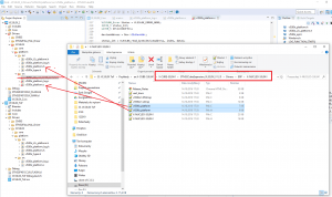
We’re close 🙂 Now similarly copy the pair vl53l0x_platform_log. h and .c this time from the path ..\X-CUBE-53L0A1\STM32CubeExpansion_VL53L0X_V1.2.0\Drivers\BSP\Components\vl53l0x.
These files are responsible for logging the API operation on the platform. By default they are disabled, and the ones from the API were written for Windows. I have not tested their operation.
If you compile now, you will probably have one error left. The compiler cannot find stm32xxx_hal.h to include it in vl53l0x_platform.h and .c. The platform files were written some time ago when the HAL files were named slightly differently.
It’s enough to replace the line #include “stm32xxx_hal.h” in the files vl53l0x_platform.h and .c with the appropriate header for your microcontroller. In my case, for the F4 family it will be #include “stm32f4xx_hal.h”.
Now compilation went through without errors. We should also run a simple measurement.
Using the API for a single measurement
If you haven’t previously included the header vl53l0x_api.h in main.c, do it now. Then you will need a few variables for the sensor to work.
VL53L0X_RangingMeasurementData_t RangingData;
VL53L0X_Dev_t  vl53l0x_c; // center module
VL53L0X_DEV    Dev = &vl53l0x_c;
The first is the structure with measurements. The second is the device structure. The third is a pointer to the structure from point no. 2.
For initialization you need a few helper variables. I put them in user section no. 1.
  /* USER CODE BEGIN 1 */
	//
	// VL53L0X initialisation stuff
	//
    uint32_t refSpadCount;
    uint8_t isApertureSpads;
    uint8_t VhvSettings;
    uint8_t PhaseCal;
  /* USER CODE END 1 */
and the sensor initialization
  /* USER CODE BEGIN 2 */
  MessageLen = sprintf((char*)Message, "msalamon.pl VL53L0X test\n\r");
  HAL_UART_Transmit(&huart2, Message, MessageLen, 100);

  Dev->I2cHandle = &hi2c1;
  Dev->I2cDevAddr = 0x52;

  HAL_GPIO_WritePin(TOF_XSHUT_GPIO_Port, TOF_XSHUT_Pin, GPIO_PIN_RESET); // Disable XSHUT
  HAL_Delay(20);
  HAL_GPIO_WritePin(TOF_XSHUT_GPIO_Port, TOF_XSHUT_Pin, GPIO_PIN_SET); // Enable XSHUT
  HAL_Delay(20);

  //
  // VL53L0X init for Single Measurement
  //

  VL53L0X_WaitDeviceBooted( Dev );
  VL53L0X_DataInit( Dev );
  VL53L0X_StaticInit( Dev );
  VL53L0X_PerformRefCalibration(Dev, &VhvSettings, &PhaseCal);
  VL53L0X_PerformRefSpadManagement(Dev, &refSpadCount, &isApertureSpads);
  VL53L0X_SetDeviceMode(Dev, VL53L0X_DEVICEMODE_SINGLE_RANGING);

  // Enable/Disable Sigma and Signal check
  VL53L0X_SetLimitCheckEnable(Dev, VL53L0X_CHECKENABLE_SIGMA_FINAL_RANGE, 1);
  VL53L0X_SetLimitCheckEnable(Dev, VL53L0X_CHECKENABLE_SIGNAL_RATE_FINAL_RANGE, 1);
  VL53L0X_SetLimitCheckValue(Dev, VL53L0X_CHECKENABLE_SIGNAL_RATE_FINAL_RANGE, (FixPoint1616_t)(0.1*65536));
  VL53L0X_SetLimitCheckValue(Dev, VL53L0X_CHECKENABLE_SIGMA_FINAL_RANGE, (FixPoint1616_t)(60*65536));
  VL53L0X_SetMeasurementTimingBudgetMicroSeconds(Dev, 33000);
  VL53L0X_SetVcselPulsePeriod(Dev, VL53L0X_VCSEL_PERIOD_PRE_RANGE, 18);
  VL53L0X_SetVcselPulsePeriod(Dev, VL53L0X_VCSEL_PERIOD_FINAL_RANGE, 14);
  /* USER CODE END 2 */
At the beginning I introduce myself 😉 Next it’s important to initialize the fields in the Dev structure. You need to specify which I²C you’re using by providing a reference to the HAL handle structure. You also provide the sensor address (which, in fact, cannot be changed).
Then I toggle the XSHUT pin. It’s a bit over the top, but I can.
Finally, the sensor is initialized to operate in single-measurement mode. I took this from the examples for Windows 🙂 They turned out to be useful after all. As you can see, we initialize some timing and range constants. These sensors are really quite elaborate, and I’ll analyze this in more depth.
After all this initialization, you can put the measurement in the main loop of the program.
	  VL53L0X_PerformSingleRangingMeasurement(Dev, &RangingData);

	  if(RangingData.RangeStatus == 0)
	  {
		  MessageLen = sprintf((char*)Message, "Measured distance: %i\n\r", RangingData.RangeMilliMeter);
		  HAL_UART_Transmit(&huart2, Message, MessageLen, 100);
	  }
Unfortunately, this is a blocking measurement that doesn’t use the interrupt pin. However, it works! The measurement is in millimeters.
The value RangingData.RangeStatus contains information on whether the measurement succeeded. A nice thing to filter out bad readings.
You’ll find the distance under RangingData.RangeMilliMeter.
Some measurements and numbers
I wouldn’t be myself if I didn’t peek at the analyzer, right? First, the entire measurement “cycle”. Fortunately, the interrupt pin is toggling all the time, so it’s easier for me to capture the appropriate timing.
100 kHz

400 kHz

Between successive “interrupts” there’s 41 ms for 100 kHz and 36 ms for 400 kHz. According to the documentation, sampling and computing the distance takes ~31 ms, so adding I²C transmission time could fit. As you can see, quite a bit of data goes over the bus. The smaller bars are polling the sensor to check whether it’s finished. That’s obvious when we operate in polling mode. However, there are two wider bars. The first is the measurement start.
100 kHz

400 kHz

3.14 ms for 100 kHz vs 0.84 ms for 400 kHz. That matches the theory 🙂
All that remains is to check how long the MCU takes to collect the measurement.

100 kHz400 kHz

2.8 ms for 100 kHz vs 0.795 ms for 400 kHz.
As you can see, there’s quite a lot of data to collect from such a sensor. Ideally, you’d bring in interrupt mode, and best together with DMA. For now, I don’t know if the API supports this. I’ve already spent some time wrestling with getting it to run.
Code size
At the beginning I mentioned that this API is somewhat heavy. In the table I included bare code with configured peripherals without the API and code with the API. Both versions with optimization -O1 and without -O0. Here are the numbers.
| -O0 | -O1 | |
|---|---|---|
| Bare code | 8,73 KB | 5,57 KB |
| with API | 36 KB | 22,52 KB |
As you can see, this API weighs a bit… Is it worth it? I’m not yet able to answer that. I’ll try to do something with interrupts or DMA 🙂
Summary
The VL53L0X sensor is nice, small, but somewhat complicated. The API helps a lot, but it costs a lot of space on the microcontroller. I’ll still check what possibilities there are for using this library with interrupts or DMA.
There are also Arduino libraries written based on this API. I’ve seen that they’re a bit lighter. I might take a look at them as well.
You can find the second part with interrupt handling here
You can find the full project along with the library, as usual, on my GitHub: link
If you’ve noticed an error, disagree with something, would like to add something important, or simply feel like discussing this topic, write a comment. Remember that the discussion should be polite and in accordance with the rules of the Polish language.
Podobne artykuły





0 Comments