STM32 microcontrollers undoubtedly have many killer features. Of course, compared to the ancient AVRs that are still used in the most popular Arduino Uno. One of those things is that STMs have a built-in real-time clock, RTC for short. Let me show you in detail what working with such a clock looks like using the HAL library generated by CubeMX.
Some time ago I described external RTC chips (DS3231, DS1307 and PCF8563). They were connected via the I²C interface and generated interrupts every second. Depending on the chip, they had either battery-backed SRAM memory or, for example, oscillator signal correction, making them extremely accurate. They also had hardware date handling inside.
First of all, I will focus on the RTC built into the STM32F103C8T6 chip, i.e. the popular BluePill. More or less consciously, this is the first choice for beginners.
You have to remember that this is one of the first RTC implementations used in STM32. It doesn’t have many functions or extensive registers, as you’ll see in a moment.
RTC in the STM32F103
The clock circuit in its basic purpose is supposed to measure time, the human, watch-like one. In the F103, only one counter is used to count time/date. It is a 32-bit register that counts only the number of seconds. I told you it’s a simple RTC, right?
Alright, but what do we need seconds alone for?! We want hours, minutes, and even the date like we had with dedicated external chips. What a piece of junk…
It’s true that this single counter may look idiotic at first glance. However, it’s not as stupid as it might seem. I don’t know if you know, but in Linux-family systems time and date are also counted this way.
Because it’s implemented on a single counter, the programmer is free to decide what format they want to work with RTC in. You can use the time.h library and work with UNIX time or WinCE.
Of course you can write your own RTC handling if you feel up to it. I highly recommend doing something like that. You can learn a lot along the way 🙂
You can also use ST’s library, which is included in the project generated by CubeMX. It works a bit differently than the UNIX standard. That’s the library I’ll focus on in the near future.
Battery backup
An interesting feature built into the RTC are the backup registers. In the F103 there are (as many as!) 10 of them. All are 16-bit, so you can store 20 bytes of data. Seems like little, right?
These registers are battery-backed when the supply voltage disappears or the microcontroller enters low-power modes. Due to special battery backup, access to them is controlled by a special bit.
In normal power mode, these registers operate from the voltage applied to VDD. The microcontroller reset circuit detects VDD loss and switches to VBAT power for the backup registers and also several special blocks. In total these are:
Backup Registers
RTC – the clock can keep running
LSI – internal oscillator for driving the RTC
PC13 – Tamper detection
Thanks to this, full RTC functionality is preserved after disconnecting the main power supply.
Tamper detection
There is also something called Tamper detection. Tamper in English means to meddle. It is detection of tampering with a device 🙂
How does it work in the STM32F103? The RTC has a special PC13 pin that is battery-backed, and can be configured as RTC_TAMPER. This pin can be connected to some kind of limit switch. After detecting the configured edge on this pin (for example, when someone opens the enclosure), an Event is triggered that clears the entire contents of the Backup Registers.
Importantly, the Tamper event also works from battery power.
To be honest, I’ve never used this mechanism. If you have any interesting application and a real example of use, describe it in the comments.
RTC Alarm
Our RTC built into the STM32F103 has a simple alarm. There is a dedicated 32-bit register for this purpose. You write the alarm value there and if the value from the main RTC counter equals the alarm value, an interrupt will be generated.
Test platform
As I mentioned earlier, I will demonstrate RTC operation on the well-known and liked BluePill board with the STM32F103C8T6. This is currently my only STM32F1 platform that I own.
The software I will use is:
STM32CubeIDE v1.2.0
STM32CubeMX v 5.5.0 built into the IDE
HAL F1 v 1.8.0
Configuration in CubeMX
For testing purposes, besides RTC I need a few other things.
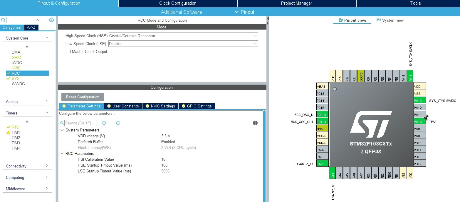
First, clocks:
I set HCLK to the maximum value of 72 MHz using the external HSE oscillator.
As the RTC clock source, first choose LSI – later I’ll show you how to switch to LSE
For debugging purposes I used:
UART2 in 115200 8n1 configuration
Serial Wire in the System Core > SYS > Debug > Serial Wire tab
GPIO input PA10 labeled as TEST
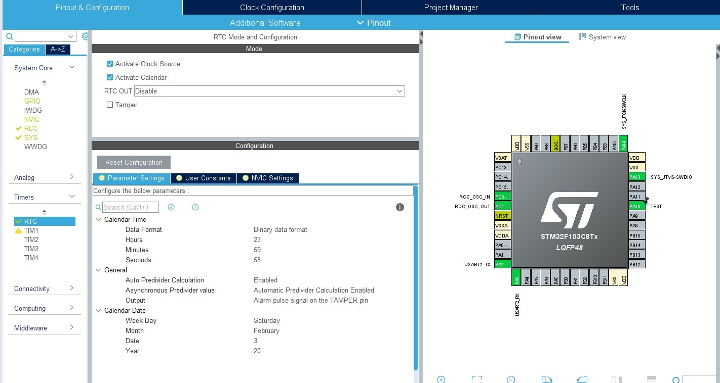
Now you can configure the RTC. It is located in the tree under Timers.
Check Activate Clock Source – to enable the RTC and provide the clock source. Also enable the calendar with the second checkbox. Wait, wait! I said there is no calendar here, right? What’s going on?
This will be a software calendar provided by ST’s library 🙂
Below are the RTC settings. You can set the factory time and date. You enter the year in the 0–99 range, without hundreds and thousands.
Also switch Data Format to binary. There will be no need to convert from BCD to “human” numbers and back later.
In the fields under General, leave everything at default: automatic prescaler calculation (convenience) and Alarm on the TAMPER pin (it doesn’t matter for us at this moment).
You can generate the project 🙂
RTC code
We got ST’s library to work with, which also implements a software calendar. To operate on the RTC you need to create two instances of structures – time and date. Let me omit the additional elements related to sending data over UART.
RTC_TimeTypeDef RtcTime;
RTC_DateTypeDef RtcDate;
Each of these structures has fields responsible for each element of date and time.
typedef struct
{
  uint8_t Hours;            /*!< Specifies the RTC Time Hour.
                                 This parameter must be a number between Min_Data = 0 and Max_Data = 23 */

  uint8_t Minutes;          /*!< Specifies the RTC Time Minutes.
                                 This parameter must be a number between Min_Data = 0 and Max_Data = 59 */

  uint8_t Seconds;          /*!< Specifies the RTC Time Seconds.
                                 This parameter must be a number between Min_Data = 0 and Max_Data = 59 */

} RTC_TimeTypeDef;

typedef struct
{
  uint8_t WeekDay;  /*!< Specifies the RTC Date WeekDay (not necessary for HAL_RTC_SetDate).
                         This parameter can be a value of @ref RTC_WeekDay_Definitions */

  uint8_t Month;    /*!< Specifies the RTC Date Month (in BCD format).
                         This parameter can be a value of @ref RTC_Month_Date_Definitions */

  uint8_t Date;     /*!< Specifies the RTC Date.
                         This parameter must be a number between Min_Data = 1 and Max_Data = 31 */

  uint8_t Year;     /*!< Specifies the RTC Date Year.
                         This parameter must be a number between Min_Data = 0 and Max_Data = 99 */

} RTC_DateTypeDef;
So it’s easy to reference them. Notice that the date also has the day-of-week number. You don’t have to fill it in manually. When updating the date, it is calculated and written automatically.
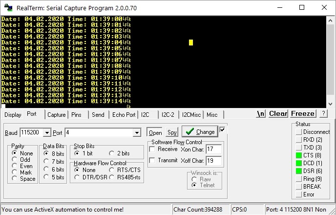
Now in the main loop you can easily read the date and time.
And that’s it. Now it’s enough to send it over UART. I added a small mechanism where I send to UART only when the second changes. We don’t need an avalanche of data on the serial port.
When you reset the microcontroller, you’ll notice that the date and time returned to those set from Cube. On the Internet you can find countless threads devoted to this terrible “bug”.
I’m not sure if it can be called a bug at all. It’s normal library behavior. It’s like if you wrote in main before the main loop that you want to set some date and expected it not to change between resets. It will be the same.
How to fight it? After all, this is generated using Cube. Deleting the lines that set the time and date won’t help when you regenerate the code in Cube. When you need to regenerate the code after some time, I guarantee you’ll forget about it and you’ll look for the problem from scratch. That’s not how we do it!
If you look into the RTC initialization code in the rtc.c file, you’ll notice that right before setting the date and time there is a special user section. That’s exactly what you will use.
Insert a simple return here. It won’t let the microcontroller reach the point where RTC is set, so time will run as it did before the reset. Beautiful!
void MX_RTC_Init(void)
{
  RTC_TimeTypeDef sTime = {0};
  RTC_DateTypeDef DateToUpdate = {0};

  /** Initialize RTC Only
  */
  hrtc.Instance = RTC;
  hrtc.Init.AsynchPrediv = RTC_AUTO_1_SECOND;
  hrtc.Init.OutPut = RTC_OUTPUTSOURCE_ALARM;
  if (HAL_RTC_Init(&hrtc) != HAL_OK)
  {
    Error_Handler();
  }

  /* USER CODE BEGIN Check_RTC_BKUP */
  //
  //	You have to do not let Init code to reinitialize Time and Date in RTC.
  //	It's "a bug" in HAL widely described and complain on forums.
  //	That causes every MCU restart the time and date will be same as you configured in CubeMX.
  //	All you have to do is just return before init time/date in this user section.
  //
    return;
  /* USER CODE END Check_RTC_BKUP */

  /** Initialize RTC and set the Time and Date
  */
  sTime.Hours = 23;
  sTime.Minutes = 59;
  sTime.Seconds = 55;

  if (HAL_RTC_SetTime(&hrtc, &sTime, RTC_FORMAT_BIN) != HAL_OK)
  {
    Error_Handler();
  }
  DateToUpdate.WeekDay = RTC_WEEKDAY_SATURDAY;
  DateToUpdate.Month = RTC_MONTH_FEBRUARY;
  DateToUpdate.Date = 3;
  DateToUpdate.Year = 20;

  if (HAL_RTC_SetDate(&hrtc, &DateToUpdate, RTC_FORMAT_BIN) != HAL_OK)
  {
    Error_Handler();
  }

}
Now after reset the time is remembered, but the date isn’t…
Problems with the date
The date is not remembered because it is not a component of the hardware RTC! Additionally, ST’s library does not treat the hardware RTC counter as date + time. It is used only for counting seconds, and when the counter rolls over – the day is reset.
The date structure is just a variable in SRAM that the library stores. So it’s normal that after a microcontroller reset it will be cleared!
You can fight it. Remember the Backup Registers? Exactly with them.
However, I’ll deal with that next time, because this post has already become quite large.
Summary
As you can see, you won’t use the RTC right away the same way you would with those in dedicated ICs. Even though configuration in Cube and usage are quite easy, a problem appeared with the disappearing date and the lack of keeping it when power is removed.
But don’t worry! In the next article I’ll show you how to deal with it. I’ll also cover switching to work with an external crystal, because that will also bring a certain surprise 😉
You can find the full project along with the library, as usual, on my GitHub: LINK
If you noticed an error, disagree with something, would like to add something important, or simply feel like you’d like to discuss this topic, write a comment. Remember that the discussion should be polite and in accordance with the rules of the Polish language.
5/5 - (1 vote)
Podobne artykuły
Measuring Air Quality with the SDS011
Addressable WS2812B LEDs on STM32, Part 1
Radio Communication Using nRF24L01+ Modules, Part 1
Darmowy ebook
Dołącz do mojej listy mailowej aby otrzymać darmowy ebook "Pierwsze kroki z STM32".
Udało się!
Potwierdź w emailu dołączenie do mojego newslettera!
In mid-July 2025, together with several leading creators from the embedded industry, we had the opportunity to visit the STMicroelectronics factory in Agrate, Italy. How did it happen? …well, I know 😅 This visit had Read more
UART Communication on STM32. Transmission to PC | STM32 on Registers #6 We have already learned the basic operations on GPIO, as well as ways to delay individual tasks. Today we will go beyond the Read more
Doing 3 Things at Once, or How to Implement a Software Timer? | STM32 on Registers #5 Let’s get to know one of the effective ways not to block the processor’s work by waiting. It Read more
The msalamon.pl blog uses cookies. By using the website, you consent to the use of cookies. More information can be found on the Privacy Policy page. Do not acceptAccept
Privacy Policy & Cookies
Privacy Overview
This website uses cookies to improve your experience while you navigate through the website. Out of these cookies, the cookies that are categorized as necessary are stored on your browser as they are essential for the working of basic functionalities of the website. We also use third-party cookies that help us analyze and understand how you use this website. These cookies will be stored in your browser only with your consent. You also have the option to opt-out of these cookies. But opting out of some of these cookies may have an effect on your browsing experience.


0 Comments