Model hobby servomechanisms, or servos for short, are a very interesting type of actuator. They move around an axis, similar to regular motors, except the rotation is not continuous. The mechanism rotates only by a “given angle.” In other words, with a servo you set the position in which it should be. Supplying voltage alone is not enough. A servo requires
a “special” signal.
How to approach it?
What is this mysterious signal? It is nothing more than a PWM signal (Pulse Width Modulation). The control unit in a servomechanism requires a 50 Hz signal for proper operation, i.e., with a period of 20 ms. The high state in this signal should be in the range of 1÷2 ms. Theoretically, 1 ms corresponds to a deflection of about -90°, 1.5 ms to 0°, and 2 ms to +90°. That’s in theory. In practice, it varies.
This time I took a micro-size servo — Turnigy TG9e — to the bench. It’s very popular, mainly because of its low price. Obviously — larger ones are more expensive. My patient has tiny plastic gears, which already suggests it was designed to transmit rather small forces. The spec lists a torque of 1.5 kg/cm. It’s enough to move linkages in a small RC model 🙂
According to the spec I found online, the supply voltage should be in the range of 4.8÷6 V. Fortunately, Nucleo boards have 5 V power pins. What about the signal then? The spec unfortunately does not state that it can be driven at 3.3 V 🙁 The STM32 won’t drive 5 V from a GPIO, but it’s always worth trying with 3.3 V 😉
First ticker

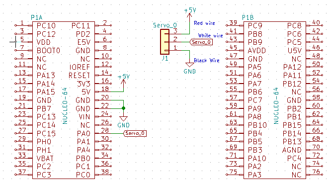
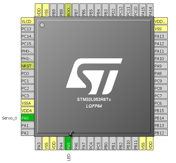
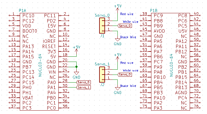
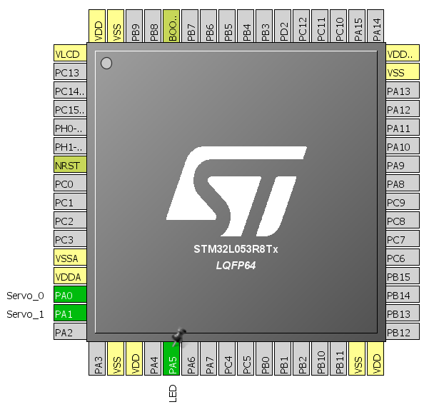
For testing I used a Nucleo64 with the L053R8. The schematic is not complicated. Unfortunately, servos don’t have numbered pins on their connector. You need to follow the color code. Red is power, black or brown is ground, and orange or white is the control signal. There are probably other colors, but the shade convention is always similar. I happen to have two servo models in red-black-white.
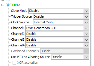
The wiring is done. Now I need to configure Cube. How to generate the PWM signal? You could torture yourself with GPIO and calculate when to change the pin state. I do not recommend this approach — don’t even try it! To generate PWM, you primarily use timers. STM32, like any respectable microcontroller, has several such timers. In the STM32L053R8 example, 3 out of 4 timers have a PWM mode and together they offer 8 channels you can use for this purpose. I chose TIM2. I selected an external clock source for the timer, and on channel one I chose PWM generation.
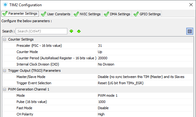
You still need to set the prescaler and the number of counted pulses. In my example, the MCU runs at 32 MHz and that clock also reaches the timers. The signal period should be 20 ms. Hence, I would like the counter to count to a multiple of that number. 32 MHz divided by 20 gives 1.6 MHz. If we raise the counting resolution by one order, getting a tick of 1 µs and a counting period of 1.6 kHz. 1600 Hz / 50 Hz = 32, so the main clock still needs to be divided by that much. I’ll do this in the prescaler. Remember that you enter a value reduced by 1 here, i.e., 31 in this case. You can also enter in the Pulse field a value corresponding to the servo control range. I entered 1000, i.e., the equivalent of 1 ms for the above timer settings. These calculations may seem chaotic, but with a little practice it goes fairly smoothly 🙂 As you gain experience, many operations related to calculating timer parameters become obvious at first glance.
With Cube set up this way, it can generate the code skeleton that I’ll use to handle the servo. The servo library I wrote is quite small. Basically, we only give the servomechanism the deflection angle. The entire library is three functions. Initialization, to which you need to pass a structure created for each servo, a pointer to the timer associated with the servo, and the PWM channel of that timer.
void Servo_Init(servo_t *servo, TIM_HandleTypeDef *_htim, uint32_t _channel);
For the servo in the Cube configuration above, initialization looks like this:
Servo_Init(&servo1, &htim2, TIM_CHANNEL_1);
The remaining two functions set the servo to a given position — one for integer angles, the other for fractional.
void Servo_SetAngle(servo_t *servo, uint16_t angle);
void Servo_SetAngleFine(servo_t *servo, float angle);
At the beginning of the header file I placed definitions for the Turnigy TG9e servo I used. They are associated with the maximum deflection values and the corresponding timer values. Each servomechanism model has different maximum capabilities, and I determined these parameters empirically. They are not determined with surgical precision.
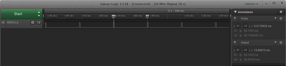
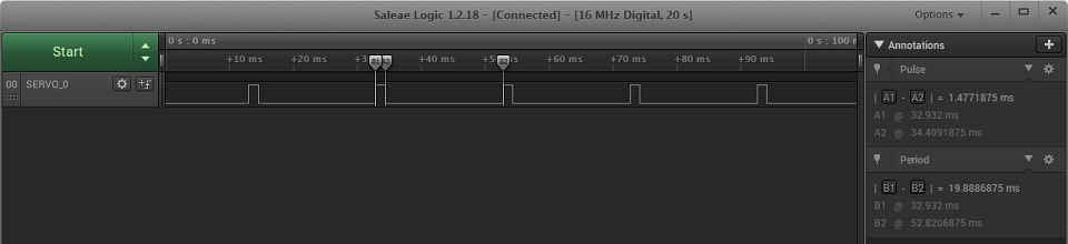
What does the waveform look like for a servomechanism? Classically like PWM. Servo deflections of 0°, 90°, and 180° respectively:
How to connect a second servo?
With a wire — how else? The most convenient way is to use an already configured timer, which exposes up to four PWM channels. I used the second channel for another servo. If you need to use a different timer, you unfortunately need to configure that timer in a similar way. Configuring the second channel for a servo is trivially simple. Just set the pin and enable Channel2 in the TIM2 options tree.

In code, you need to declare another variable for the servo and initialize it.
Servo_Init(&servo1, &htim2, TIM_CHANNEL_1);
Servo_Init(&servo2, &htim2, TIM_CHANNEL_2);
I compile and woo-hoo! It works 🙂
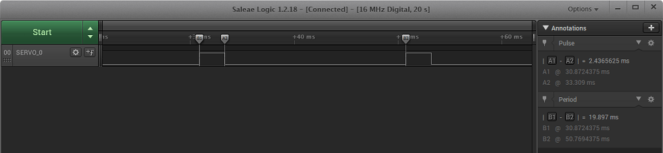
PWM for two servos looks like this:
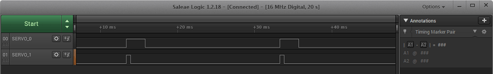
The deflections are independent. The only common element is the starting point of the high state. All PWMs based on one timer will have this common feature.
And more servos?
Increasing the number of servos in a system can be tempting, for example when building a spider robot. Connecting each individual servo to PWM outputs of the timers may not be the best solution then. What instead?
One option could be the PCA9685. By default, it is an LED PWM driver, but with the right setup and configuration it will easily handle servos. Our Chinese friends manufacture boards dedicated to servos, and I’ll focus only on that aspect. What can these modules do?

According to the datasheet (
PCA9685 Datasheet
), the PCA9685 has 16 PWM channels. It can be powered over a wide voltage range of 2.3 ÷ 5.5 V, which makes it suitable for use with STM32. Each LED output can be loaded with 25 milliamps at 5.5 V.
This controller has a programmable PWM frequency ranging from 24 to 1526 Hz, with each output having the same PWM frequency. The duty cycle can be controlled in the 0÷100% range at 12-bit resolution, giving 4096 steps.
The PCA9685 communicates over the I²C interface. Interestingly, the chip has built-in noise suppression for the SDA and SCL lines. The maximum SCL clock frequency is 1 MHz. Additionally, the chip provides 6 bits of address configuration. This allows you to connect 64 such chips, enabling control of up to 1024 servos!
For more details about the chip itself, please refer to the datasheet.
The board you get is adapted for driving servos. For each servo there is a 3‑pin connector, additionally color-coded for power and signal. The power for the servos is separated from the chip’s power and is supplied through a screw terminal. Thanks to this, we can run logic at 3.3 V and servos at 5 V. Since there can be as many as 16 servos, and quite large ones at that, you should use an external power supply.
Schematic and Cube configuration

This time I’ll use a Nucleo with STM32F401RE. For some time now, CubeMX has been generating a unified set of headers for all microcontroller families, so there are no problems with porting between individual MCUs. The connection is trivial.
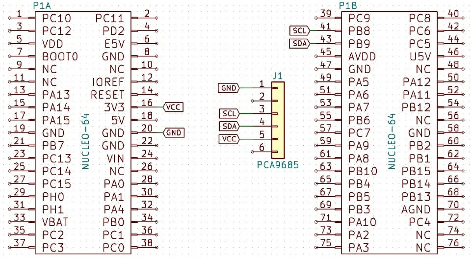
In Cube, activate I2C1 at whatever speed you want. That’s enough.
PCA9685 code
The PCA9685 is quite extensive. It allows, among other things, setting different PWM frequencies. Remember that this frequency is identical for each of the 16 channels. However, you can set a different start and end point of the pulse for each channel, i.e., you can, for example, shift some outputs.

However, I’ll start from the beginning. The first thing you need to do if you want to control servos is to uncomment the definition in the header.
#define PCA9685_SERVO_MODE
This is a small convenience that configures the PWM to the appropriate value and exposes the servo functions while simultaneously blocking access to the PWM frequency change functions.
As usual, the first function you need to call in main is initialization. It resets the chip, sets up PWM, and enables auto-incrementing of register addresses, which makes it easy to write data to the PCA9685.
PCA9685_STATUS PCA9685_Init(I2C_HandleTypeDef *hi2c);
When using the chip with servos, two functions will be of interest. The first is
PCA9685_STATUS PCA9685_SetPin(uint8_t Channel, uint16_t Value, uint8_t Invert);
It sets a PWM signal of a given length. You can also invert the PWM, but for a servo this is somewhat unnatural. To use this function, you need to know the values to enter. The chip accepts a maximum value of 4096, but the useful range for a servo is about 110÷500, defined as SERVO_MIN and SERVO_MAX for the test Turnigy TG9e. Theoretically, this range allows movement over 0÷180º (actually -90º to +90º). In practice, I noticed that each servo has a slightly different range.
Unfortunately, you need to think a bit about which deflection corresponds to a specific PWM value. It will be much easier to work in angular deflection values. There is an appropriate function for this.
PCA9685_STATUS PCA9685_SetServoAngle(uint8_t Channel, float Angle);
It is much simpler to use. The angle provided as an argument does not need to be an integer, hence I used a float. To use this function, you must have the range definitions for the servos used and the corresponding angles defined correctly.
There is nothing stopping you from using my library to control LEDs. Just comment out PCA9685_SERVO_MODE, and you can even use it if a 50 Hz PWM frequency is suitable. Finally, here’s a short demo of the PCA9685 in action.
Summary
As you can see, servomechanisms are very easy to use. With a dedicated PWM module, they are even easier. Applications? Anywhere you need to move something 😀 In modeling, these are, for example, airplane control surfaces, steering, etc. You can try making a door lock or even a clock using servos. Feel free to share your idea in the comments.
I’ve always had in mind building a servo-based manipulator. One with robot kinematics baked in, not with millions of potentiometers like Arduino projects. What do you think?
You’ll find the test codes along with libraries on my GitHub: PWM, PCA9685
Finally, I encourage you to discuss handling an LCD display on STM32 in the comments. Do you think I made a mistake somewhere? Do you have an interesting idea for improvement? Share it in the comments! Remember that the discussion should be civil and in accordance with the rules of the Polish language.

Podobne artykuły


0 Comments