Not long ago I wrote an article about how to implement UART reception via DMA. I successfully wrote such a “hands-free” implementation for STM32F411. Many of my readers also use cheap boards with F103 and porting the library caused huge problems. I adapted my code and I will show you what the differences were and the potential difficulties.
First, I encourage you to read the post for STM32F411, in which I described in detail how I managed to implement UART reception via DMA. In this post I only deal with porting this method to the STM32F103C8 at the request of readers.
Differences between F4 and F1
Among the significant differences I would mention just one. It is the DMA module, which plays an important role in reception. In STM32F1 series microcontrollers, DMA is more “limited”. Each DMA module contains only a few channels through which we can fetch data. In the F103C8 there are 12 channels in total.
STM32F4 has a bit more “bells and whistles” in DMA. Since I already mentioned channels, you can sense that this is where the difference lies, right? In F4 we have something called Streams. The F411RE has as many as 16 of these streams (8 for each of the two DMA controllers). Each such stream consists of up to 8 channels. This is one of the main differences that can cause trouble when porting.
Since we have a more extensive DMA, of course there will be different registers responsible for everything. In my code, I partially used “bare” registers. I will discuss the exact differences alongside the code.
There is one more important “small” difference. Do you remember that “trick” where stopping DMA would automatically trigger a transfer-complete interrupt? This is true only for Streams, i.e., e.g., F4 microcontrollers. For the STM32F103, stopping the DMA channel will unfortunately not trigger such an interrupt.
STM32CubeIDE – configuration
Let’s start with the configuration in CubeIDE. The version I use is v1.1.0 with integrated CubeMX v5.4.0, while the HAL libraries are F1 v1.8.0.

As a test platform I used the well-known BluePill, which you can buy from a reliable source — from me 🙂
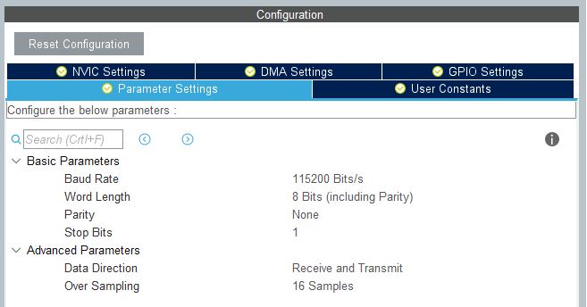
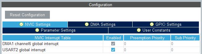
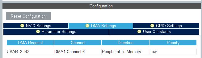
The configuration is very similar to the one from the previous post, which concerned the F4 family. You need to configure UART2 (or another) to 115200 Bits/s and enable the DMA channel for reception on this UART. In addition, you need to enable global UART2 interrupts to be able to use the IDLE interrupt.
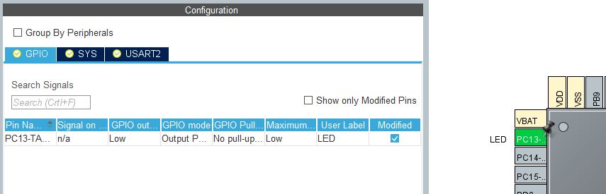
Besides that, you need a few more things. Set pin PC13 as output. It has the on-board LED, which we will control with UART commands.
Finally, enable Debugging via Serial Wire – it makes work much easier 😉
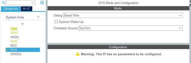
and set a higher HCLK clock. I used 64 MHz.
Code
You can generate the project configured like this. I’ll start with the main.c file. Nothing changes here compared to the F4 code. You initialize the library in the same way and simply parse the data coming from UART2.
  /* USER CODE BEGIN 2 */
  UARTDMA_Init(&huartdma, &huart2);
  /* USER CODE END 2 */

  /* Infinite loop */
  /* USER CODE BEGIN WHILE */
  while (1)
  {
	  if(UARTDMA_IsDataReady(&huartdma))
	  {
		  UARTDMA_GetLineFromBuffer(&huartdma, ParseBuffer);
		  if(strcmp(ParseBuffer, "ON") == 0)
		  {
			  HAL_GPIO_WritePin(LED_GPIO_Port, LED_Pin, GPIO_PIN_RESET);
		  }
		  else if(strcmp(ParseBuffer, "OFF")  == 0)
		  {
			  HAL_GPIO_WritePin(LED_GPIO_Port, LED_Pin, GPIO_PIN_SET);
		  }
	  }
    /* USER CODE END WHILE */

    /* USER CODE BEGIN 3 */
  }
  /* USER CODE END 3 */
}
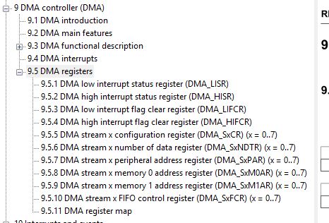
Trying to copy the library from F4 will end with lots of errors. Remember to insert the interrupt handler code properly. The errors result from the aforementioned differences between DMA in both microcontrollers. This is what the register tree looked like for the F411
And this is for today’s hero – F1
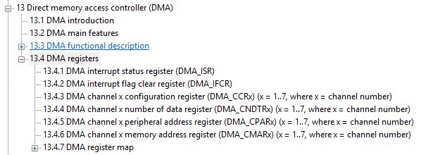
You can see that the difference is quite large. However, it only looks scary at first glance. Many functions of the registers overlap but are named differently. You can notice similarities such as DMA_LISR/DMA_HISR and DMA_ISR. The double register results from the greater number of statuses in F4.
Let’s get rid of the compiler errors!
“Incorrect” register names
The most common error will be an unknown register or bit name that we use. Let’s go from the top of the file. The first thing that shows up is
huartdma->huart->hdmarx->Instance->CR &= ~DMA_SxCR_EN;
The compiler does not know the CR register or the DMA_SxCR_EN bit. Looking into the F411 reference manual, we can see that this is the Stream configuration register, to which we write the negated bit to enable DMA. We are in the UART IDLE interrupt function, so this is simply disabling DMA after receiving a string of characters.
What needs to be done? Find how the register and bit responsible for the same thing are called in F103! As I said, the registers have similar names. In fact, most of them differ in that in F411 they are called “Stream X…”, and for F103 “Channel X…”. That’s exactly the case for the CR register, i.e., the Configuration Register.
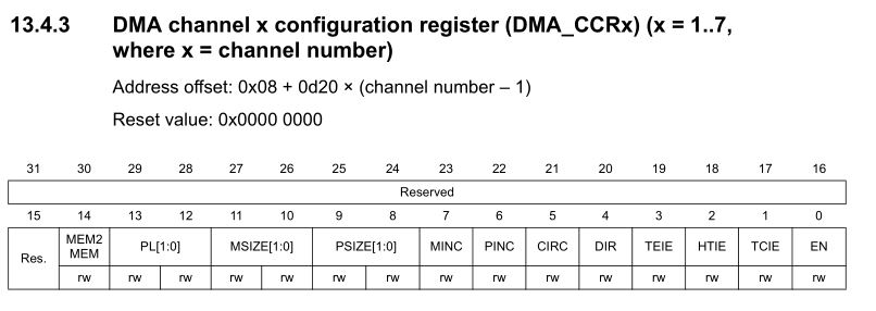
A quick look at the Reference Manual and we already know that the register is abbreviated as CCR, and the bit enabling DMA is EN. According to the HAL naming convention, the erroneous line should be corrected to
huartdma->huart->hdmarx->Instance->CCR &= ~DMA_CCR_EN;
And the compiler leaves it alone. Bring on the next problem. This time the compiler complains that it doesn’t know StreamBaseAddress. This is a member of the HAL DMA structure. No wonder it doesn’t know it, because in F1 there are no Streams. Logically, this variable is a pointer to the base address of the DMA stream. It should be changed to DmaBaseAddress. I found this by browsing the definition of that structure.
So replace
DMA_Base_Registers *DmaRegisters = (DMA_Base_Registers *) huartdma->huart->hdmarx->StreamBaseAddress;
with
MA_Base_Registers *DmaRegisters = (DMA_Base_Registers *) huartdma->huart->hdmarx->DmaBaseAddress;
However, here you might not notice something. A moment earlier such a structure was defined
typedef struct
{
__IO uint32_t ISR; // DMA interrupt status register
__IO uint32_t Reserved0;
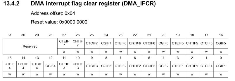
__IO uint32_t IFCR; // DMA interrupt flag clear register
} DMA_Base_Registers;
These are the base registers, i.e., the status and interrupt clear registers. Between them there is one Reserved0 field. Why? Notice that in F411 you have two registers. There are “high” and “low” ones. A total of 64 bits for status and clearing. In the structure this was represented in such a way that after the 32-bit LISR there are another 32 bits, which can be treated as the next part of the total “virtual” 64-bit ISR register.
In F103 you don’t have “upper” and “lower” registers. There is only one ISR and IFCR. Therefore, you can remove this reservation so that the names match what they will point to.
typedef struct
{
	__IO uint32_t ISR;   // DMA interrupt status register
	__IO uint32_t IFCR;  // DMA interrupt flag clear register
} DMA_Base_Registers;
Now we have a slightly different problem. The compiler reports that in the line
maRegisters->IFCR = DMA_FLAG_TCIF0_4 << huartdma->huart->hdmarx->StreamIndex;
there are two errors. An unknown flag and a shift. A quick look at the documentation lets you notice that the DMA_FLAG_TCIF0_4 flag is the Transfer Complete flag for Stream 0 or 4 depending on which register we are dealing with in F4. It’s easy to see that you need to replace it with its F1 equivalent, i.e., DMA_IFCR_CTCIF1. The StreamIndex variable is not known to the compiler for exactly the same reason as a bit above it didn’t know the base address of the DMA registers. Just replace Stream with Channel to get the following
DmaRegisters->IFCR = DMA_IFCR_CTCIF1 << huartdma->huart->hdmarx->ChannelIndex;
Next there is a visible problem with the register that stores the number of items remaining to be transferred by DMA. Here it’s simple, because according to the documentation
Length = DMA_RX_BUFFER_SIZE - huartdma->huart->hdmarx->Instance->NDTR;
is enough to change to
Length = DMA_RX_BUFFER_SIZE - huartdma->huart->hdmarx->Instance->CNDTR;
The last differences in the DMA interrupt handling can be found at its exit. There are lines related to clearing the DMA interrupt, setting the memory address for DMA to write to, setting the number of data to transfer via DMA, and starting the DMA itself.
In each of them the compiler returns errors.
DmaRegisters->IFCR = 0x3FU << huartdma->huart->hdmarx->StreamIndex; 		// Clear all interrupts
huartdma->huart->hdmarx->Instance->M0AR = (uint32_t) huartdma->DMA_RX_Buffer; // Set memory address for DMA again
huartdma->huart->hdmarx->Instance->NDTR = DMA_RX_BUFFER_SIZE; // Set number of bytes to receive
huartdma->huart->hdmarx->Instance->CR |= DMA_SxCR_EN;            	// Start DMA transfer
After the earlier explanations, you should be able to handle them already. Maybe with one small exception…
You can notice the mysterious value 0x3F written to the IFCR register. In this register, interrupt flags are cleared by writing a one to the appropriate place. So why 0x3F? It comes from the fact that the first 6 flags refer to one Stream in F4. This value is shifted left by the StreamIndex to select the appropriate flags.

In F1 there are fewer of these flags, only 4, so you will have to write 0x0F to the appropriate register.
Searching and matching all the names for F1, the whole thing comes down to the following
DmaRegisters->IFCR = 0x0FU << huartdma->huart->hdmarx->ChannelIndex; 		// Clear all interrupts
huartdma->huart->hdmarx->Instance->CMAR = (uint32_t) huartdma->DMA_RX_Buffer; // Set memory address for DMA again
huartdma->huart->hdmarx->Instance->CNDTR = DMA_RX_BUFFER_SIZE; // Set number of bytes to receive
huartdma->huart->hdmarx->Instance->CCR |= DMA_CCR_EN;            	// Start DMA transfer
In the entire code there is only one incorrect line left during the initialization of the UARTDMA library. It concerns disabling the half-transfer interrupt. The name of the register and the bit changes, of course.
In F4 it was like this
huartdma->huart->hdmarx->Instance->CR &= ~DMA_SxCR_HTIE; // Disable DMA Half Complete interrupt
and in F1 it is like this
huartdma->huart->hdmarx->Instance->CCR &= ~DMA_CCR_HTIE; // Disable DMA Half Complete interrupt
A simple change 🙂
Will it work?
Not yet! Do you remember how I wrote a little higher that for DMA with channels like in F103 the Transfer Complete interrupt will not be triggered after stopping DMA? What to do? I came up with simply manually calling the interrupt handling function before exiting the interrupt handling the UART IDLE.
The whole function will therefore look like this
void UARTDMA_UartIrqHandler(UARTDMA_HandleTypeDef *huartdma)
{
	if(huartdma->huart->Instance->SR & UART_FLAG_IDLE)       // Check if Idle flag is set
	{
		volatile uint32_t tmp;
		tmp = huartdma->huart->Instance->SR;                      // Read status register
		tmp = huartdma->huart->Instance->DR;                      // Read data register
		huartdma->huart->hdmarx->Instance->CCR &= ~DMA_CCR_EN; 	  // Disable DMA - it will force Transfer Complete interrupt if it's enabled
																  // BUT! It's only for DMA Streams(i.e F4), not for Channels like there in F103!
		tmp = tmp; // For unused warning
		UARTDMA_DmaIrqHandler(huartdma); // Since DMA IRQ won't start independently for Channels, we have to handle it manually
	}
}
However, remember that the UARTDMA_DmaIrqHandler(huartdma) function should also be placed in the Transfer Complete interrupt handler. Although we assume that messages should be shorter than the DMA buffer, it may happen that something longer arrives (life verifies :)). Then there is a danger that the DMA buffer will fill up and you will not yet receive the UART IDLE interrupt. In this case, clearing the DMA buffer will be performed in the Transfer Complete interrupt.

Summary
Was porting from F411 to F103 that difficult? Yes and no… Changing the registers themselves was easy. It was worse to come up with the idea that the DMA TC interrupt would not be triggered after “manually” disabling DMA. At first I didn’t know what was going on that the interrupt didn’t “wake up” 🙂 However, everything ended well and you get from me a ready-made guide to such porting and code for the BluePill 😉

(this online course is conducted in Polish)
The full project along with the library can be found as usual on my GitHub: link
If you noticed any error, disagree with something, would like to add something important, or simply think you’d like to discuss this topic, write a comment. Remember that the discussion should be polite and in accordance with the rules of the Polish language.
Podobne artykuły


0 Comments