Recently I focused my attention on the insanely accurate RTC DS3231. It does not require an external crystal and additionally has built-in temperature compensation. However, there are plenty of other real-time clocks on the market. They don’t necessarily boast about being accurate. Let’s take a closer look at what they offer and how to deal with them.
DS1307
DS1307 is one of the most popular RTCs. It’s usually the first one that pops up in search engines. It has also been described in every possible way. There are plenty of ready-made modules with this chip. You can buy one of these modules in my store.
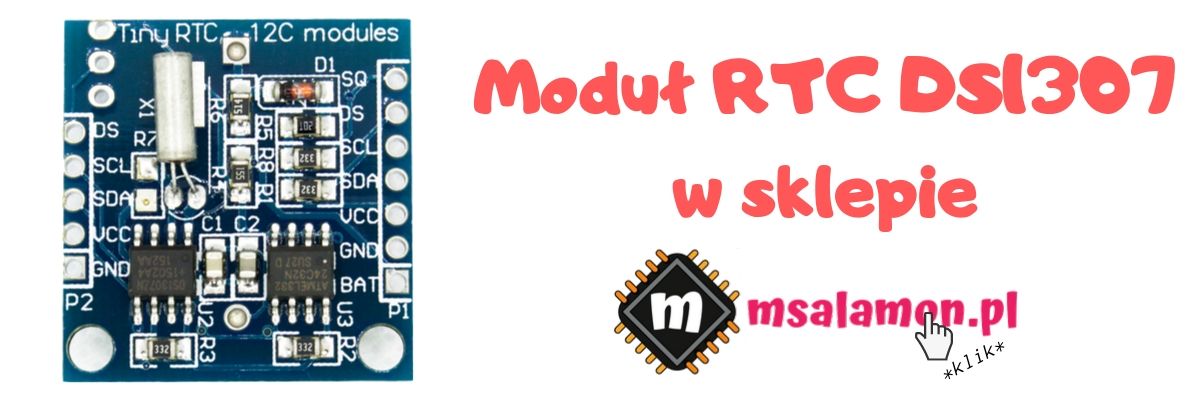
Its success undoubtedly lies in its price. It’s an insanely cheap chip. Even though it requires a few additional external components, it’s still financially worth it.
Additionally, using the DS1307 is very simple, as I’ll show in a moment.
First, I wanted to show you how it differs from the DS3231 from the previous post. The first thing that stands out is the supply voltage. Unfortunately, the DS1307 only tolerates around 5 V. If you want to use it with an STM32, you need two voltages (fortunately, both are available on Nucleo). Luckily, the STM32 tolerates 5 V on its inputs, so there’s nothing to worry about on that side. I2C is, fortunately, open-drain, so there is no problem translating 3.3 -> 5 V for the DS1307.
Another limitation compared to the accurate DS3231 is the I²C interface speed. With the DS1307 you’ll get guaranteed stability only up to a 100 kHz clock. Sad face 🙁
There’s also no way to change the I²C address. There’s one fixed address. Exactly the same as on the DS3231.
It also lacks an alarm function, but I’m not crying over that. I’ve never used it. Maybe one day I’ll finally need it.
Alright, but is there anything positive? There is 🙂 The DS1307 has 56 bytes of battery-backed RAM. A very cool feature when you need to store some data while putting the microcontroller into the deepest power-saving modes.
Connecting and programming the DS1307
Today, just like with the DS3231, I used the Nucleo F410RB. The wiring is completely simple, just like in the previous post.
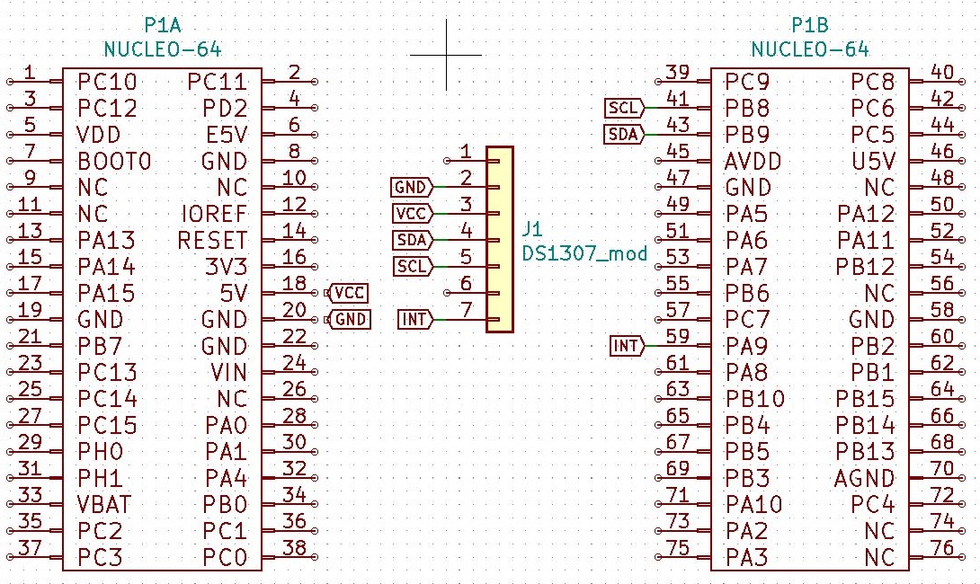
For the software I used STM32CubeIDE version 1.0.2 and the HAL F4 library version 1.24.1.
Exactly like in the previous post, I wrote non-blocking handling via DMA. The code is surprisingly similar, because the registers holding the date and time in almost every RTC look the same or similar. I’m curious about the I²C transfer times.
I’ll skip the Cube configuration because it is the same as for the DS3231 — I²C with DMA, an EXTI interrupt on a single edge, and UART for printing to the terminal.
Remember, however, that the DS1307 tolerates a maximum of 100 kHz on the I²C clock, so set it accordingly.
DS1307 code
I’d like to focus only on the differences compared to the DS3231. During initialization, it is required to enable the clock driving the chip, because after connecting power the RTC will not start counting on its own. It’s an interesting method of a controlled clock start. You can also nicely use this to count working hours in a device. Additionally, I set the SQW pin to a 1 Hz square wave so that the interrupt works as expected.
void DS1307_Init(I2C_HandleTypeDef *hi2c)
{
	hi2c_ds1307 = hi2c;

	DS1307_SQWRateSelect(SQW_RATE_1HZ);
	DS1307_SQWEnable(1);
	DS1307_ClockHalt(0);
}
You must remember to override the callback functions for DMA as well as the EXTI interrupt. You can do this in the fourth user code section in the main.c file.
void HAL_GPIO_EXTI_Callback(uint16_t GPIO_Pin)
{
	if(GPIO_Pin == DS1307_INT_Pin)
	{
		DS1307_ReceiveDateTimeDMA();
	}
}

void HAL_I2C_MemRxCpltCallback(I2C_HandleTypeDef *hi2c)
{
	DS1307_CalculateDateTime(&r);
}
And that’s it for handling the library. Simple and pleasant as always 🙂
An addition I mentioned earlier is the battery-backed RAM. I wrote simple functions to write to this memory.
void DS1307_ReadRAM(uint8_t Address, uint8_t *Value, uint8_t Length);
void DS1307_WriteRAM(uint8_t Address, uint8_t *Value, uint8_t Length);
The RAM address range you can use is 0x08 ÷ 0x3F.
DS1307 performance
Let’s check how it behaves both in a blocking interrupt and via DMA.
100 kHz interrupt

100 kHz DMA

The handling time is 916 µs in the interrupt vs 301 µs with DMA.
PCF8563
Another popular chip is the PCF8563. There are modules for it as well, which you can buy in my store.
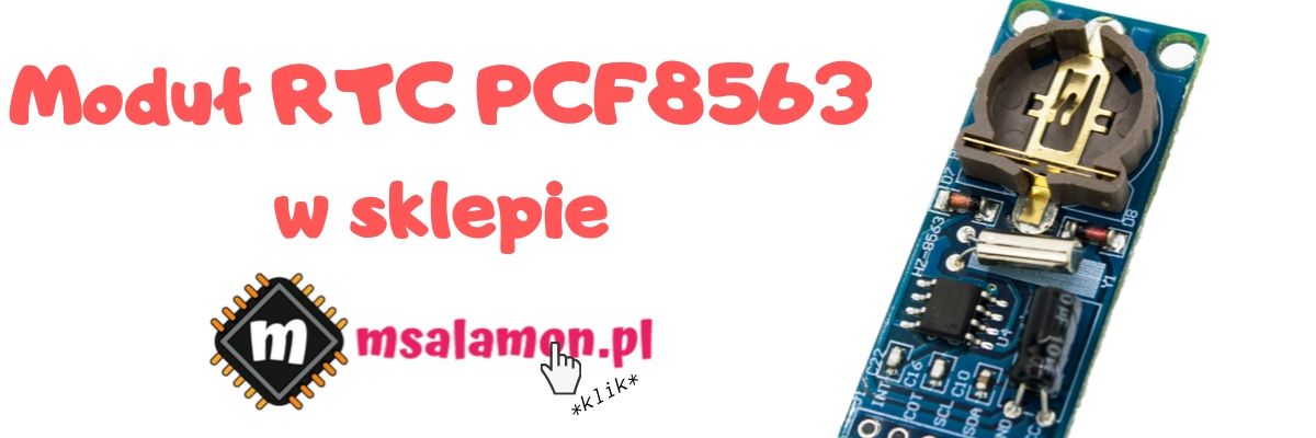
What makes this chip stand out? It can be powered incredibly low. For proper I²C communication, 1.8 V is enough. This value allows you to use this RTC in circuits aimed at extremely low power consumption.
Additionally, the chip happily accepts 400 kHz on the I²C clock.
The module has an alarm function and an interesting 8-bit countdown Timer feature. After counting down, it can assert an interrupt. A cool gadget for those who are short on timers in the microcontroller.
Connecting and programming the PCF8563
The connection is analogous to the above.
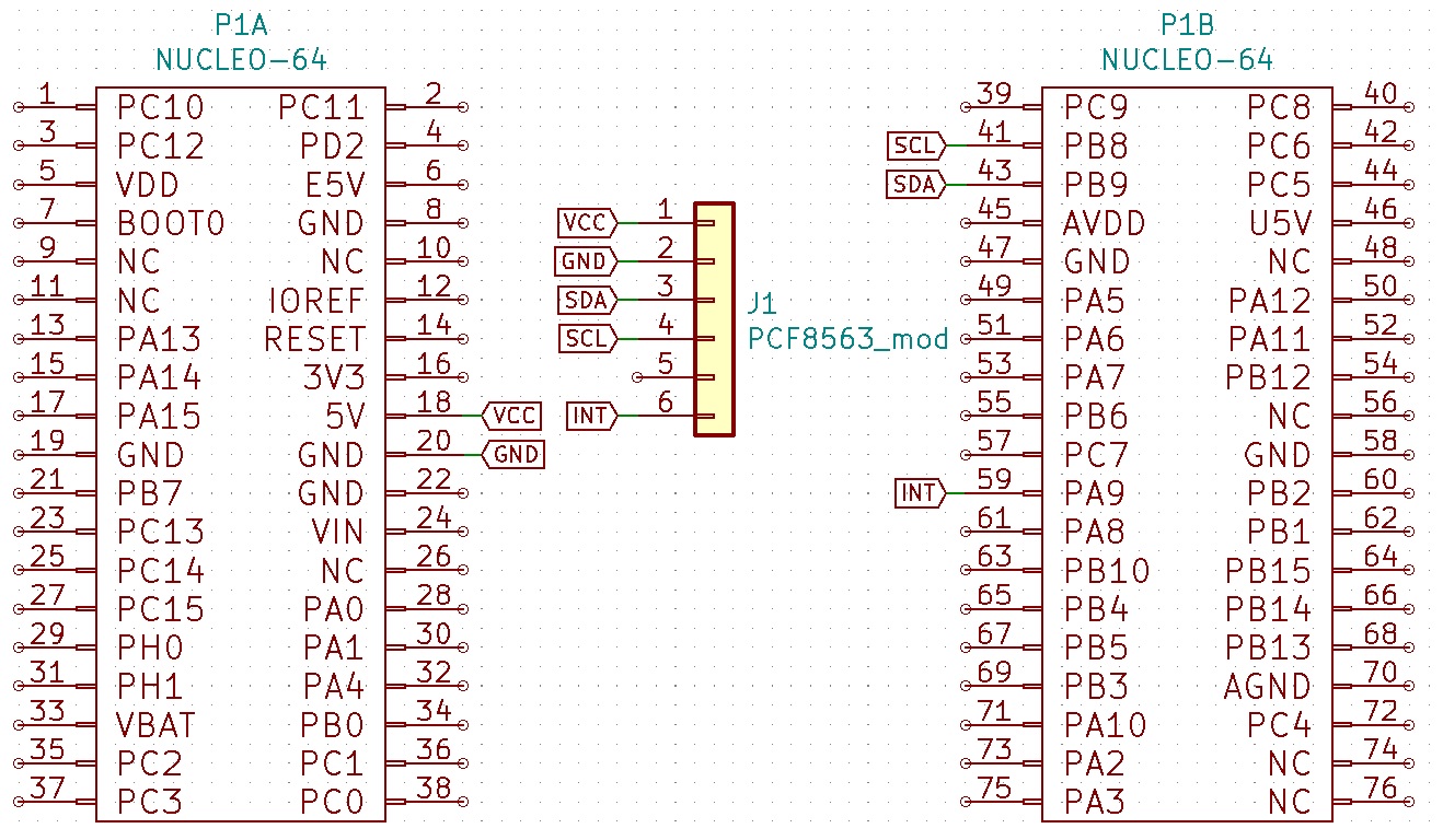
Cube configuration? No changes 🙂 Okay, there will be one. The PCF8563 allows operation at 400 kHz on the I²C clock line, so use that if you’re at 100 kHz.
PCF8563 code
Quite possibly you’ve already guessed what it will look like. Of course, it’s similar to the previous code. I did not implement the alarm and built-in Timer. If you feel like it, I’ll be happy if you contribute to my repository.
From a user perspective, it is of course enough to initialize the RTC and read data in the interrupt or via DMA. During initialization, I set the 1 Hz output signal from the chip and, although the clock starts by default after applying power, I clear the STOP bit to be sure.
void PCF8563_Init(I2C_HandleTypeDef *hi2c)
{
  hi2c_pcf8563 = hi2c;

  PCF8563_ClkoutFrequency(CLKOUT_FREQ_1HZ);
  PCF8563_STOPEnable(0);
}
DMA receive handling is analogous to the previous examples. The entire handling is contained in the fourth USER CODE section.
void HAL_GPIO_EXTI_Callback(uint16_t GPIO_Pin)
{
  if(GPIO_Pin == PCF8563_INT_Pin)
  {
    PCF8563_ReceiveDateTimeDMA();
  }
}

void HAL_I2C_MemRxCpltCallback(I2C_HandleTypeDef *hi2c)
{
  PCF8563_CalculateDateTime(&r);
}
PCF8563 performance
Let’s look at the waveforms for reading in a blocking interrupt and via DMA.
100 kHz interrupt

400 kHz interrupt

100 kHz DMA

400 kHz DMA

I’ll now compare these results with those obtained for the DS3231 and DS1307.
Comparison of various RTCs
I gathered all the results in a table.
| DS3231 | DS1307 | PCF8563 | |
|---|---|---|---|
| 100 kHz INT | 919 µs | 916 µs | 924 µs |
| 400 kHz INT | 237 µs | X | 308 µs |
| 100 kHz DMA | 301µs | 301 µs | 302 µs |
| 400 kHz DMA | 85 µs | X | 107 µs |
As you can see, the results between the individual chips are close to each other. I’m wondering about the 400 kHz DMA time. Why is there a visible difference of about 20 µs when issuing the DMA transfer? The SysTick interrupt has the same priority, so I exclude interference from it. Perhaps the analyzer introduced some error. Nonetheless, the results are comparable.
Summary
I checked two other popular RTCs that you can use in your projects — DS1307 and PCF8563. Both in theory are not paragons of accuracy, which I have not yet tested experimentally. Maybe I’ll do such a test soon 🙂
It’s worth using faster I²C transmission and DMA communication. You can save a lot of valuable time. I’ve encountered a small complaint that some DMA channel is always occupied. That’s what it’s for — to use it. Unless it’s needed for more important things. Then you can do another trick.
STM32 has a built-in RTC. It does have a lousy RC oscillator with an error of a few percent, but it can be clocked by an external oscillator. Thanks to this you’ll offload the DMA. That’s also worth checking.
The full project along with the library can be found, as usual, on my GitHub: DS1307, PCF8563
If you noticed an error, disagree with something, would like to add something important, or simply feel like discussing the topic, write a comment. Remember that the discussion should be polite and in line with the rules of the Polish language.
Podobne artykuły





0 Comments