Ask anywhere which temperature sensor to use and the answer you’ll most often get is DS18B20. Dallas’s chip is extremely popular. You can also buy a waterproof version in stores, which further strengthens its popularity. Obviously, I couldn’t miss this sensor.
Communication with DS18B20
You can talk to the DS18B20 only via the 1-Wire interface. What is that?! It’s an invention by Dallas Semiconductor, which later merged with Maxim. This interface, which is also a protocol, uses only a single line for bidirectional communication, hence its name.
I don’t want to go into the details of this interface and how it works. In short, the most important information is:
-
- All devices are connected to a single bus.
- Ones and zeros are defined as pulses with time constants defined by the interface. Because of this, the communication speed is essentially fixed.
- Transmission is serial and follows the master-slave rules.
- The protocol includes addressing, thanks to which we can activate a selected sensor, similar to I²C.
I recommend the official Maxim documentation, which explains the details much better than I would. On the company website there are, for example, some helpful articles: Link1 Link2
Connection
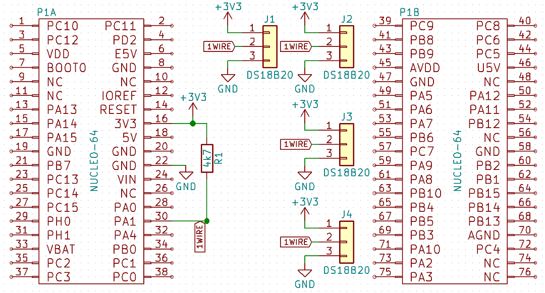
As I mentioned earlier, devices on the 1-Wire bus are connected with only one wire. Adding power, we typically have 3 wires. The data line must be pulled up to the supply line through a resistor. It is usually 4k7 ohm.
Hmm, I said 3 wires by default. And non‑standard? Two! Namely, the 1‑Wire interface allows communication in the so‑called parasitic mode, where the positive supply line is not provided to the sensor. The VDD pin on the Slave device is then shorted to ground. So where does the sensor get its power from? As the name of the mode implies – it parasitizes on the data line. In 1‑Wire slave devices there is a capacitor that, when a high state appears on the data line, charges and maintains the supply during the low state.
For the purposes of this post I used the regular mode. I connected 4 DS18B20 sensors to pin PA1 on the Nucleo F401RE.

Programming
On the Internet you can find tons of 1‑Wire communication examples for probably all microcontrollers in the world. I won’t pretend my library is unique or written from scratch. When writing it I relied on various open examples that are publicly available. I made a library that suits me in use. I’m not claiming it’s the best – it’s good 🙂
For the library to work you need a timer with a 1 µs tick. It’s easy to obtain by using an integer number of megahertz to clock the MCU. Just set the prescaler to (MCU clock) – 1. Remember to enter a large value – e.g., 65000 – into the Counter Period of the timer configuration in CubeMX.
The library consists of two parts. The first is the 1‑Wire interface handling. It is hands‑off and does not require any configuration in headers. The second part is, of course, DS18B20 handling. Configuration in the header file includes:
- The maximum number of DS18B20 devices that can be connected to the bus.
- The GPIO pin and port used for 1‑Wire.
- The name of the handler for the timer with a 1 µs tick.
- A define flag that decides whether to use CRC. You can save a few bytes of time when reading at the possible cost of data correctness.
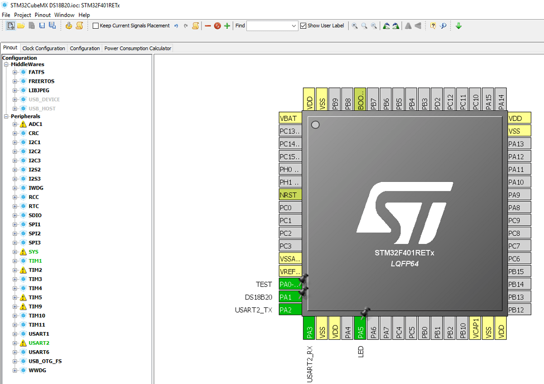
Configuration in CubeMX is trivially simple. Just define the GPIO bus pin as a regular GPIO Output and configure the aforementioned timer. Additionally, I threw in the on‑board Nucleo LED for blinking, a UART for printing temperatures to the PC, and a test output for viewing on a logic analyzer.
How does my code work? Information about each connected sensor is stored in an array of Ds18b20Sensor_t structures with the number of elements given in the header as the maximum number of sensors. It contains information about the full address, the last correctly read temperature, and the success of the last read. Additionally, I created a variable that says how many DS18B20 sensors were detected. There may be fewer than the MAX defined in the header. I wondered about dynamically allocating memory for the number of connected sensors, but would that make sense? In general their number doesn’t change during the device’s lifetime, so the number of elements in the array can be set fixed.
Access to data such as address or temperature is possible only through dedicated functions. There is no manual poking around in the structure. The most important functions:
void DS18B20_Init(DS18B20_Resolution_t resolution);
This is, of course, initialization. Inside the initialization, the 1‑Wire bus is started and DS18B20 sensors that are connected are searched for and counted. You must pass the required resolution for the devices as an argument. Remember that resolution has a huge impact on the time it takes to convert the temperature to digital form. Available options:
DS18B20_Resolution_9bits
DS18B20_Resolution_10bits
DS18B20_Resolution_11bits
DS18B20_Resolution_12bits
void DS18B20_StartAll(void);
This sends the start temperature conversion command to all connected sensors. Simple.
void DS18B20_ReadAll(void);
Function to read the converted temperature into the appropriate elements in the sensor array. Every sensor detected in the initialization function is read.
uint8_t DS18B20_Quantity(void);
Returns the number of sensors detected during initialization.
uint8_t DS18B20_GetTemperature(uint8_t number, float* destination);
Writes the temperature value from the i‑th sensor to the memory location pointed to by destination.
void DS18B20_GetROM(uint8_t number, uint8_t* ROM);
void DS18B20_WriteROM(uint8_t number, uint8_t* ROM);
Operations on sensor addresses. With them, you can, for example, change the order of sensors in the array.
Putting it all together I got a sample code that prints all sensors to the terminal.
/* USER CODE BEGIN 2 */
	DS18B20_Init(DS18B20_Resolution_12bits);
/* USER CODE END 2 */

/* Infinite loop */
/* USER CODE BEGIN WHILE */
while (1)
{
	/* USER CODE END WHILE */

	/* USER CODE BEGIN 3 */
	DS18B20_ReadAll();
	DS18B20_StartAll();
	uint8_t ROM_tmp[8];
	uint8_t i;
	for(i = 0; i < DS18B20_Quantity(); i++)
	{
		if(DS18B20_GetTemperature(i, &temperature))
		{
			DS18B20_GetROM(i, ROM_tmp);
			memset(message, 0, sizeof(message));
			sprintf(message, "%d. ROM: %X%X%X%X%X%X%X%X Temp: %f\n\r",i, ROM_tmp[0], ROM_tmp[1], ROM_tmp[2], ROM_tmp[3], ROM_tmp[4], ROM_tmp[5], ROM_tmp[6], ROM_tmp[7], temperature);
			HAL_UART_Transmit(&huart2, (uint8_t*)message, sizeof(message), 100);
		}
	}
	HAL_UART_Transmit(&huart2, (uint8_t*)"\n\r", sizeof("\n\r"), 100);
	HAL_Delay(1000);
	HAL_GPIO_TogglePin(LED_GPIO_Port, LED_Pin);
}
/* USER CODE END 3 */
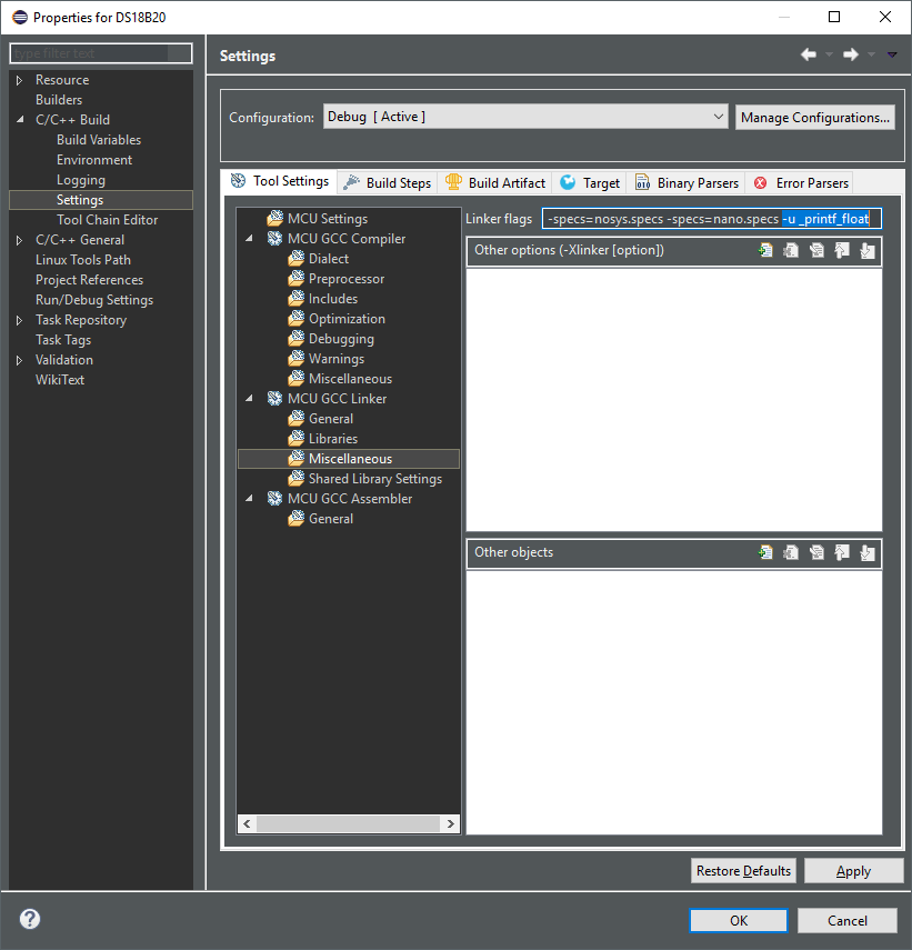
Warning, danger!!! The STM32 compiler has the quirk that after generating code in CubeMX you don’t immediately have the ability to print variables of type float! You’ll get only zeros or nothing at all 🙁 To make this work you need to add the flag -u _printf_float to the linker.
Now that everything is clear, see the result of this little piece of code:
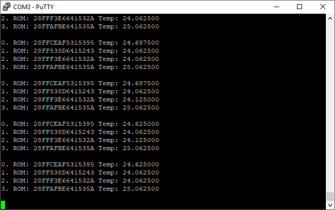
It’s warm at my desk, isn’t it? 🙂
Sooo, how long will this take?
Of course I had to check how long it takes to transfer the necessary data over 1‑Wire!

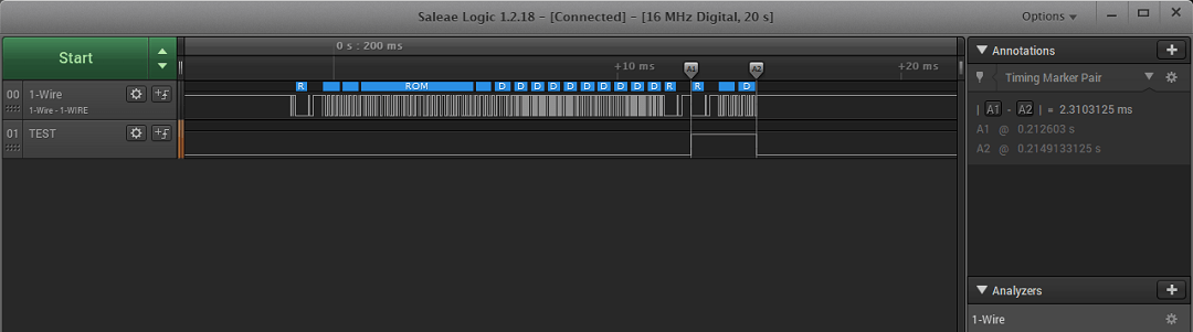
The communication to read the temperature itself takes about 14 ms.
The start conversion command for all sensors is about 2.3 ms.
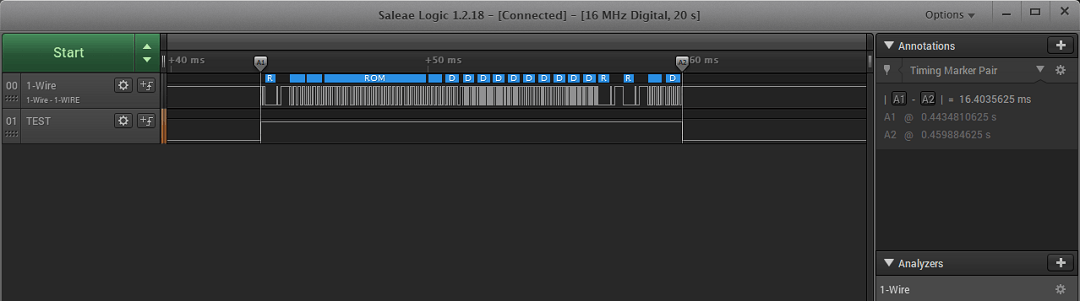
So the whole thing for one sensor is about 16.4 ms. Knowing that the start command is sent only once for all sensors, the formula for read and start conversion time for n sensors is 14 * n + 2.3 [ms]. Let’s check.

Two sensors. 14 * 2 + 2.3 = 30.3. Measurement is 30.43.
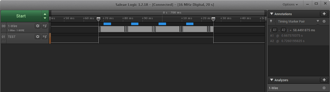
Four sensors. 14 * 4 + 2.3 = 58.3. Measurement 58.45.
So everything adds up. Can we shave off a few milliseconds? By disabling CRC.


11.75 ms for the readout of a single sensor.
The start conversion command is of course unchanged. There is nothing related to CRC here. Without CRC, the formula for handling n sensors is 11.75 * n + 2.3 [ms].

Confirmation on four sensors.
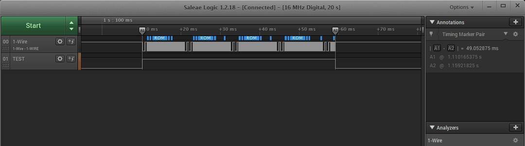
11.75 * 4 + 2.3 = 49.3. The measurement comes out 49.05. Checks out 🙂
However, be careful when giving up CRC! It may happen that you read garbage, and now you have no way to verify it.
Can we shave off more? We can, but not with the DS18B20 🙁 1‑Wire offers something called the Override mode, which speeds up transmission about 10‑fold. Our temperature sensor does not support this mode, so unfortunately I have nothing to test. In general, few 1‑Wire devices support accelerated communication.
Summary
DS18B20 temperature sensors are very pleasant. Handling them is not overly complicated, and there are thousands of examples on the Internet showing how to deal with them. I’m adding one of my own, hoping it’s written sensibly. An unquestionable advantage is the ability to handle many devices via only one data line. This works great for multi‑point measurements. Additionally, waterproof versions are perfect for measuring water temperature, e.g., in an aquarium 🙂
Thank you for reading this post. If you like this topic, let me know in a comment. I’ll also be grateful for topic suggestions you’d like me to cover.
The code is, as usual, available on my GitHub: link
If you noticed any error, disagree with something, would like to add something important, or simply feel like discussing this topic, write a comment. Remember that the discussion should be polite and in accordance with the rules of the Polish language.
Contest results
In the previous post I announced a mini contest. Time to pick the winners. From all comments that did not repeat by name, IP and email and met all requirements, I chose 10, in my opinion, most interesting uses of the display.
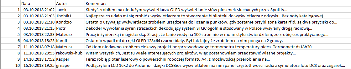
From among them I drew two winners according to the rules given in the contest. These are comments number 4 and 10 from the screenshot above. The video of the drawing is available at https://youtu.be/vqYASbZ2Xr0
Congratulations to the winners! I’ve already emailed you to finalize the contest. There will probably be more contests on the blog. I have a bit too much stuff in my closet 😉
Podobne artykuły


0 Comments