An encoder is a great device. You surely know some equipment where a knob would rotate endlessly while adjusting some parameter (e.g., an audio amplifier). A very nice idea to replace a classic potentiometer. Encoders are also very often used to measure the rotation angle of motors. In automation and robotics they are
indispensable devices. Come on, I’ll show you how easy it is to implement handling such an encoder on STM32.
How an incremental encoder works

A rotary encoder, also called an incrementer, typically has two outputs labeled A and B. As the knob rotates, square-wave signals appear on these outputs. Both waveforms form a quadrature signal. It is characterized by the two waveforms being 90 degrees out of phase. You can see such a signal in the graphic below.
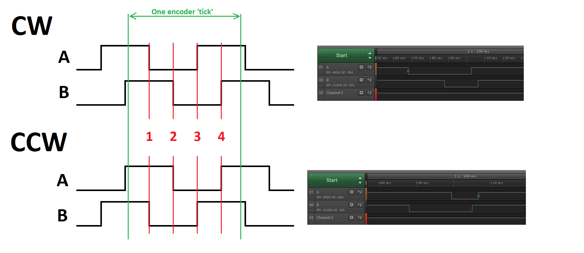
I drew two waveforms — CW and CCW. They simply denote the waveform for rotation clockwise (CW) and counterclockwise (CCW).
In green I marked the start and end of the changes that occur during one encoder detent. At rest both lines A and B are high. While the encoder is being turned, square-wave signals form at the outputs. Depending on the rotation direction, the signal begins with a falling edge on pin A for CW or on pin B for CCW. On the right I pasted how this looks in a live example from a logic analyzer.
You can notice that I marked every edge. It is on them that it’s best to detect the direction in which the lever or a motor shaft with a magnet is turning. How to determine from an edge which way the encoder is turning? You can notice a certain relationship, which I presented in the table below.
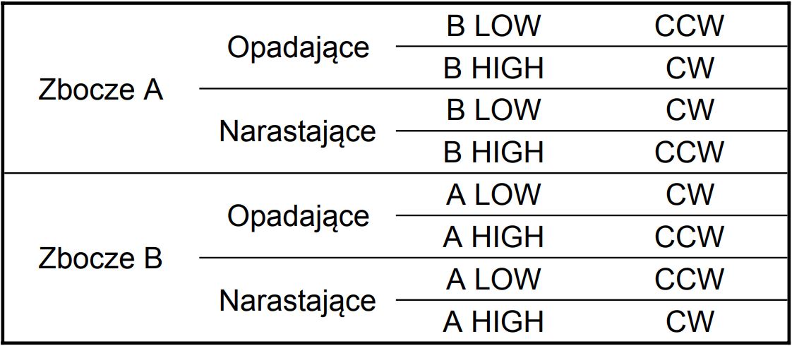
Moving from left to right in the table gives you the direction in which the encoder rotates. As you can see, you can set interrupts, for example, on the falling edge of A and check the state of line B at that moment. If it’s low, the rotation was “left”. If B was high, it rotated “right”. Simple, isn’t it?
Handling the encoder
We should handle the received encoder signal on the microcontroller. With the above table you can already write the interrupt handling. In theory it looks nice, but reality is different. A rotary encoder like this is built with mechanical switches. Do you know what that means? Yes, contact bounce… With interrupts set on a single edge it may turn out that during a single detent many more edges appear. The microcontroller is so fast that the interrupt service will be executed multiple times, yielding an unintended effect.
What can be done? You can use some debouncing method. However, such software elimination of contact bounce on an encoder is not the most convenient solution. I have a much better way out of this tough situation for you.
At hand we have, of course, the STM32. Its timers have hardware encoder support! Isn’t that beautiful? Sure it is 🙂
Hardware encoder handling on a timer

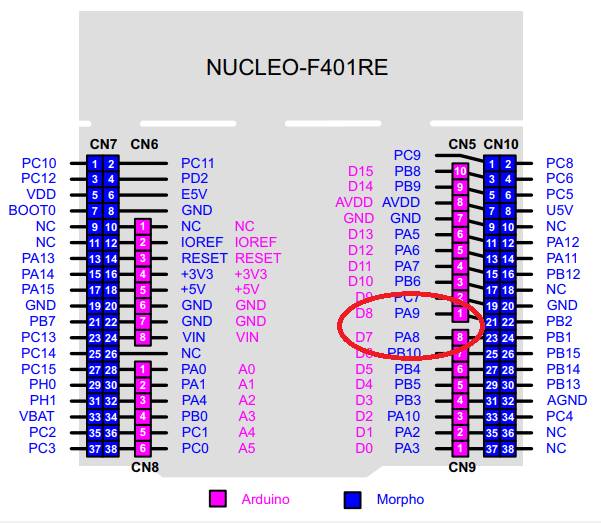
Today I’ll be working on a Nucleo with STM32F401RE. Let’s take a look at the Reference Manual of the chip. We will surely find something interesting there.
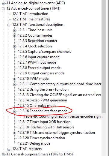
As you can see there is a timer feature called Encoder interface mode. The description takes roughly two pages, so it’s not extensive. It’s worth getting familiar with it. On the other hand, it doesn’t have to be extensive, because it’s quite a simple timer function. In the RM you’ll find which registers to configure for encoder handling to work. Fortunately, we have STM32CubeIDE with the built-in Cube, which will do it all for us. Let’s go to it.
I will configure TIM1 as the one that will read the A and B signals from the encoder. In this counter’s settings, choose the Combined Channels option and the Encoder Mode function. Most of the remaining functions of the counter will be grayed out.

On the MCU model, two pins — CH1 and CH2 — will appear configured for Timer 1. You can name them according to the connection. Some modules will have the signals marked as A and B, and some will have analogously CLK and DT.
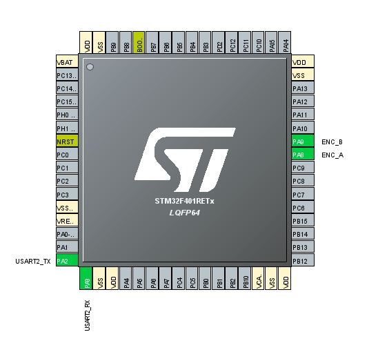
Connect the encoder appropriately to the Nucleo pins. PA8 corresponds to D7 on the Arduino header, and PA9 — to D8.
Once you have encoder mode enabled and have sorted out the connection to the Nucleo, it’s time to configure how this Timer will work. In the Configuration window you’ll find plenty of things. Fortunately, many of them won’t matter for the counter working with the encoder. I marked the settings that should interest you.

- Counter Mode – decides whether the counter will increase with CW motion or decrease.
- Counter Period – up to what value the counter will count. After exceeding it, it will roll over. You can limit this in specific applications, but I like the full 16-bit range because of the magic of binary arithmetic, as you’ll see in a moment 🙂
- Encoder Mode – Decides on which channel the pulse counting will take place. If you set only TI1 or TI2, the counter will react to edges of only one of the signals. I will set the combined mode so that it reacts to all.
- Polarity – I didn’t notice any difference for different edges. Leave it on rising.
- Input Filter – A very important parameter. It determines the length of input sampling before the counter changes. With such a hand-operated encoder, it’s worth setting it to the maximum value. This effectively eliminates the contact bounce effect.
I additionally configured UART2, which is routed to the ST-Link.
Encoder software
The code for STM32F401RE was generated using STM32CubeIDE 1.0.2 with the HAL F4 library version 1.24.1.
Configured according to the above description, Cube will generate code almost ready for action. You only need to start the timer along with all channels.
HAL_TIM_Encoder_Start(&htim1, TIM_CHANNEL_ALL);
Now every movement of the encoder will be counted and the current number of counted pulses for TIM1 is located in the CNT register of this counter.
htim1.Instance->CNT
In the main loop I put printing of this register to the terminal and… the counter increments by 4 pulses.
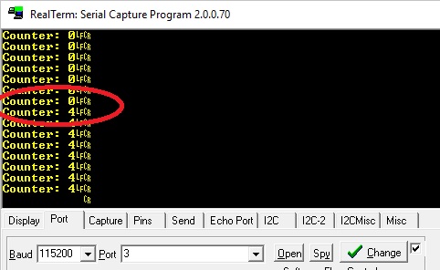
Is that a bug? Not at all! Recall the encoder mode configuration. We set it so that it reacts to edges of both signals A and B. For one encoder detent these signals will generate two edges each, so in the end the counter will count four of them. That’s where this value comes from. If you set Encoder Mode to T1 or T2, the counter will change by a value equal to 2 with each encoder click.
By rotating the encoder slowly and holding it between stable positions you can observe intermediate values on the counter — this proves that each edge is treated separately.
It’s easy to compute how many detents occurred on the encoder. Just divide by 4 and you’re done!
As you can see, handling an encoder is simple 🙂
Alright, but what do I do with that value?
Hello hello! What if I’m using an encoder as a knob to increase volume in the 0–30 range, say?! I can’t use the variable htim1.Instance->CNT as the volume value, because even if I limit counting to 30, it will wrap around! Besides, after an MCU reset this value will always be zero! How to live?
I’ll show you a trick and why I almost always recommend using the full range of the counter.
I will create a variable to store the current volume level.
int8_t AudioVolume;
You may ask why int8_t, and not the ‘classic’ uint8_t. Well, if you want to keep the 0–30 range, it will be easier to check whether the variable went below zero than whether it wrapped back to 255.
Now the whole magic. I separated a dedicated function for code readability.
void UpdateAudioVolume(void)
{
	static uint16_t LastTimerCounter = 0;
	int TimerDif = htim1.Instance->CNT - LastTimerCounter;
	if(TimerDif >= 4 || TimerDif <= -4)
	{
		TimerDif /= 4;
		AudioVolume += (int8_t)TimerDif;
		if(AudioVolume > 30) AudioVolume = 30;
		if(AudioVolume < 0) AudioVolume = 0;
		LastTimerCounter = htim1.Instance->CNT;
	}
}
Let me explain step by step how I solved it and where the magic is.
First, I created a static variable that remembers the last state of the counter at the moment of changing the volume.
static uint16_t LastTimerCounter = 0;
On each pass I check the difference between the previous counter state at the volume change and the current one
int TimerDif = htim1.Instance->CNT - LastTimerCounter;
Condition to enter the volume change. If the state changed by more than 4 (in the increasing direction) or less than -4 (in the decreasing direction), I go further.
if(TimerDif >= 4 || TimerDif <= -4)
I divide, of course, to obtain the number of individual encoder detents.
TimerDif /= 4;
And I increase/decrease the volume.
AudioVolume += (int8_t)TimerDif;
Finally, I check whether the volume fell outside the limits and I write down the current counter state.
if(AudioVolume > 30) AudioVolume = 30;

if(AudioVolume < 0) AudioVolume = 0;

LastTimerCounter = htim1.Instance->CNT;
Alright, but where is the magic? I’ll give you a hint. It’s about two special transitions of the counter htim1.Instance->CNT. These are exactly the transitions 0->65535 and in the other direction.
Why? I have zero on the counter and the last known value is also zero. I turn the encoder to the left (backwards) and what happens?
For uint16_t 0 – 4 = 65532. Now subtracting the previous value (0) from the current one (65532) we obtain for the variable TimerDif declared as int the value 65532. Now, according to the algorithm, you divide by 4 obtaining 16383 which, according to the algorithm, you add to the volume variable.
You can see that something is wrong, because you turned in the direction that should decrease the volume, and finally it is supposed to increase it by 16383! A disaster, right?
But you can notice one small detail. I cast the value of TimerDif to int8_t. For small values (from -129 to 127) it won’t matter much. BUT for a value like 16383 it already matters a lot. Do you know what the result of this cast will be? It will be… attention -1! Yes, by the magic of the counter roll-over, you will get the value you expected. Great, isn’t it?
The same will happen when rolling over in the other direction. If you don’t believe it, check on some online compiler what the result will be for casting to int8_t a variable with the value 16383.
After such a procedure it doesn’t matter from what initial value you start with the encoder, the AudioVolume variable will always behave as required. It will never go above 30 or below 0.
Summary
I showed you that handling an encoder on STM32 is trivially simple. With a simple trick you can also use the encoder for controlled modification of variables.
On the market you can find other types of encoders. Another popular type are those for counting motor rotations. These are, for example, encoders operating on a rotating magnetic field. You can handle such ones with a timer in encoder mode as well.
And what’s your opinion about encoders? Share in the comments.
You will find the full project along with the library as usual on my GitHub: link
If you noticed any error, disagree with something, would like to add something important or simply think you’d like to discuss the topic, write a comment. Remember that the discussion should be polite and in accordance with the rules of the Polish language.
Podobne artykuły


0 Comments