Inevitably, the time is coming when a red truck will roll out of the TV, and at every turn we’ll hear a beautiful song about a broken heart that the community considers the creation of a holiday mood. Yes, Christmas is coming soon and, of course, there are no holidays without
lights! Every electronics enthusiast has been pondering for months how to surprise the neighbor. Ordinary RGB LEDs have unfortunately long become commonplace, but “addressable” WS2812B LEDs come to the rescue, and for several years they have been reigning when it comes to lighting effects.
This article is part of the series:7
What are WS2812B LEDs?
These are RGB LEDs in a 5050 package with a built-in PWM controller with 8-bit resolution per color. PWM duty values are delivered digitally via just a single data line. We communicate with WS2812B LEDs using one-wire NZR communication similar to 1-Wire, except the communication for the LEDs is unidirectional. This means we can send the LED information about how it should be set, but we won’t learn from it what state it is in. Fortunately, that’s not a particular problem. What does it look like? Of course, the documentation explains everything best (
WS2812B Datasheet
). Even though it’s very short, I’ll summarize the most important information here.
The transmitted signals, just like for 1-Wire, have predefined timing constants. For complete operation we only need 3 signals: logic 0, logic 1, and RESET.
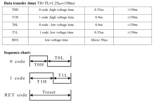
From the figure above it follows that the communication frequency is around 800 kHz.
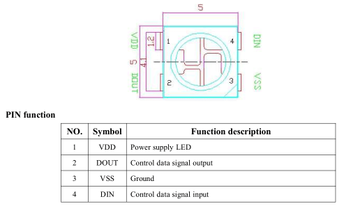
An important feature of the LEDs is the ability to chain them. The LEDs have 4 pins. Two are for power (in the range 3.5–5.3 V) and two for data—input and output. After an LED receives all the bytes it needs about colors, it automatically passes the input signal to its output. Thanks to this, they can theoretically be connected into infinite chains.
The manufacturer also notes that a 100 nF capacitor should be placed next to each LED in the chain. Strips available from the Middle Kingdom come with such capacitors.
The data write sequence to the LEDs starts with a RESET signal lasting at least 50 µs. Next come the data for the LEDs in GRB order from the first to the last LED. It’s important that the data cannot have any interruptions during transmission. From the moment an anomaly occurs, the colors will start to differ from what was intended.
STM32 code
Today I’ll be basing this on the STM32F103C8T6 found in the cheap boards from China widely known as BluePill. These Chinese modules are very popular and inexpensive. I have a few myself, so why not use them.
The microcontrollers don’t have hardware support for the interface required by WS2812B LEDs. We have to handle it another way. The first thing that comes to mind is bit-banging the GPIO. On AVR, programmers manage via the assembly instruction ‘nop’, which allows you to wait the required time to change the state in a more or less controlled way. But using nops on STM32 won’t make me write a universal and portable library—we have a lot of different MCU configurations and use many different clock speeds. I need something better. You can guard the GPIO with a Timer and change its state after specific times. Maybe that would work, but I didn’t even try that method. I came across the idea on the internet of using the MOSI signal from the SPI interface. It seemed interesting, so I started digging into it. The wiring diagram for the LED strip is trivially simple. I will use SPI number 1. Warning! Do not power directly from the STM32 module. WS2812B LEDs require around 50 mA per LED at maximum brightness. A chain of 60 LEDs/meter will therefore require around 3 A/meter at full, bright white! Supply power from an external, capable power supply.
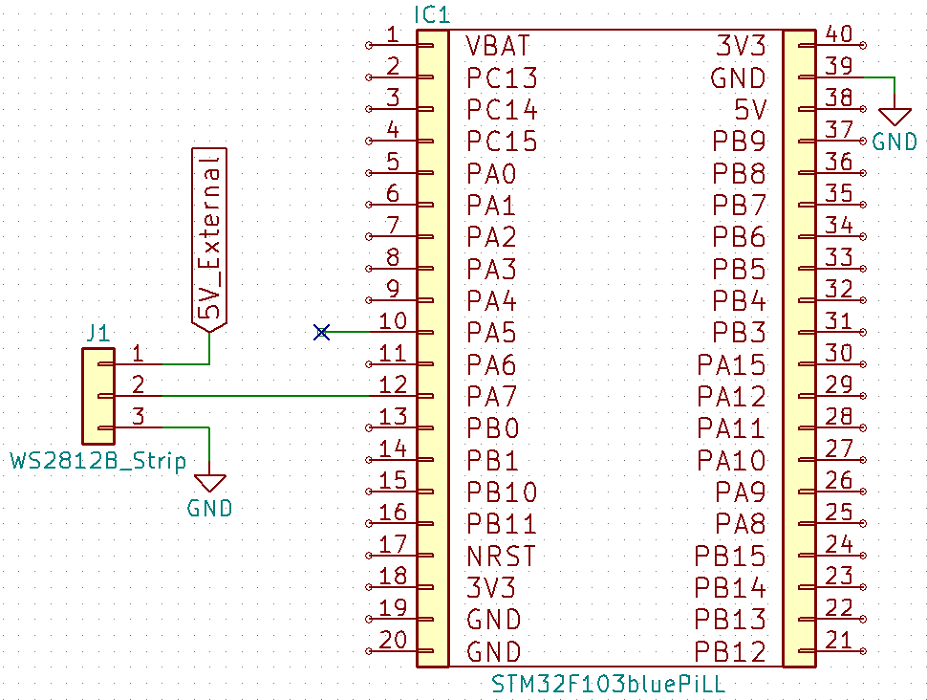
Pin PA5 serves as SCK of the SPI1 interface. It won’t be needed, but in this case it cannot be used for anything other than SPI.
To control the pulse width of the NRZ signal, I had to use an entire SPI byte as a single bit for the LED. Thus the duration of one byte should be about 1.25 µs, so one SPI bit should last about 0.156 µs. This gives an SPI clock of 6.4 MHz. In the F103C8T6 the SPI prescaler values to choose from are 2, 4, 8, 16, 32, 64, 128 and 256, which correspondingly gives the MCU clock:
- 2 * 6.4 = 12.8 MHz
- 4 * 6.4 = 25.6 MHz
- 8 * 6.4 = 51.2 MHz
- 16 * 6.4 = 102.4 MHz…

Frankly, these values are not great. It’s hard to set them like that in Cube. I encountered a claim on a certain popular forum that it MUST BE 6.4 MHz, PERIOD! Well, unfortunately, it doesn’t have to be. We have something called tolerance (after all, there’s so much fighting for it everywhere), and for WS2812B the tolerance of input signals can be ±0.15 µs, i.e., ±0.66 MHz. It will be much easier to get 6 MHz on SPI, e.g., by using a 48 MHz MCU clock and the SPI prescaler set to 8. Cube additionally suggests the SPI baud rate after selecting the prescaler. If you want a higher/lower MCU clock, look for one where the prescaler gives about 6 MHz on SPI.

6 MHz means bit durations of:
- 1 bit – 0.166 µs
- 2 bits – 0.333 µs
- 3 bits – 0.499 µs
- 4 bits – 0.666 µs
- 5 bits – 0.833 µs
- 6 bits – 0.999 µs
- 7 bits – 1.166 µs
- 8 bits – 1.333 µs
Do any of the times above match the WS2812B timing table?
For T0H, 2 bits fit (0.35 µs ±0.15), and for T1H, 5 bits fit (0.9 µs ±0.15). The rest naturally fits too 😉
Since SPI transfers from the MSB (thanks, Piotr!), the definitions of the logic states will look like this:
#define zero 0b11000000
#define one 0b11111000
For convenience, I created a structure that contains the color data for a single LED.
typedef struct ws2812b_color {
  uint8_t red, green, blue;
} ws2812b_color;
The basic library contains only three self-explanatory functions.
void WS2812B_Init(SPI_HandleTypeDef * spi_handler);
void WS2812B_SetDiodeColor(int16_t diode_id, ws2812b_color color);
void WS2812B_Refresh();
Initialization consists only of assigning a pointer to SPI to the library.
Setting an LED is done by the LED number in the chain and providing a struct variable with that LED’s colors.
Refresh sets the SPI buffer bytes according to the LED colors. It creates a big buffer containing all the data for all LEDs. Unfortunately, this eats huge amounts of RAM, but there’s a remedy for that, which I’ll get to in a moment.
Sending data
I think sending data to the LEDs is worth discussing. It’s an interesting challenge to have the data reach the LEDs in one uninterrupted stream with a small MCU overhead.
Preparing data in the buffer according to colors involves quite a lot of bit shifts, which, fortunately, are light for the MCU.
for(uint8_t i = 0; i < 72; i++)
	buffer[i] = 0x00;

for(uint16_t i=0, j=72; i<WS2812B_LEDS; i++)
{
	//GREEN
	for(int8_t k=7; k>=0; k--)
	{
		if((ws2812b_array[i].green & (1<<k)) == 0)
			buffer[j] = zero;
		else
			buffer[j] = one;
		j++;
	}

	//RED
	for(int8_t k=7; k>=0; k--)
	{
		if((ws2812b_array[i].red & (1<<k)) == 0)
			buffer[j] = zero;
		else
			buffer[j] = one;
		j++;
	}

	//BLUE
	for(int8_t k=7; k>=0; k--)
	{
		if((ws2812b_array[i].blue & (1<<k)) == 0)
			buffer[j] = zero;
		else
			buffer[j] = one;
		j++;
	}
}

HAL_SPI_Transmit(hspi_ws2812b, buffer, (WS2812B_LEDS+3) * 24, 1000);
And this works, but not quite correctly. Unfortunately, the last 3–4 LEDs on a 100-LED strip most often have random colors. This is probably because an interrupt occurs during the SPI transfer. It’s probably the SysTick Timer interrupt, but I didn’t check—there’s no point. You can disable it, but I don’t recommend it. What now? Every STM32 has something called DMA. In plain terms, it’s a peripheral with direct memory access. You can delegate to it an operation involving memory or another peripheral. Thanks to this, the MCU has time to perform other tasks, such as the SysTick interrupt that disrupted the data transfer to the LEDs.
Configuring DMA in Cube is simple. In the Configuration tab and the System table, there’s a DMA configuration button. Add a DMA configuration for SPI1_TX, which was configured earlier. Set the priority to Very High because this is a key operation. In the settings at the bottom, select Normal mode and memory increment, which in this case will be the RAM buffer.
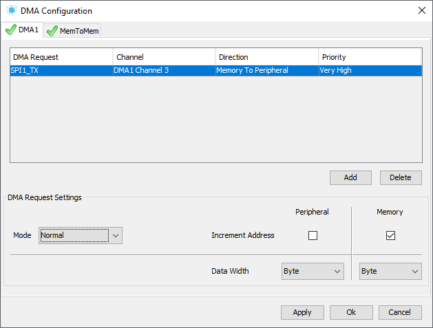
How should it work now? Only the data transfer call over SPI in the refresh function changes. Now it looks like this:
HAL_SPI_Transmit_DMA(hspi_ws2812b, buffer, (WS2812B_LEDS+3) * 24);
while(HAL_DMA_STATE_READY != HAL_DMA_GetState(hspi_ws2812b->hdmatx));
The second line waits for the transfer to complete. You can skip it, but you should do so consciously and be careful not to cause a “collision” on the DMA, because everything will break.

Now the LEDs work like a charm. Each one has exactly the color I intended.
Sending data for 35 LEDs (that’s how many I have connected for testing) is just over 1 ms, specifically 1.22 ms. The time needed to prepare the send buffer is 0.27 ms of MCU life. For simple applications, you can wait out the transfer time as I did. However, it’s worth trying to use that time for other tasks. That’s almost a millisecond with just 35 LEDs. Controlling 100 LEDs, the saved time will be about 2.8 ms, and a thousand LEDs is already 28 ms. Quite a saving, because during that time you can refresh a TFT instead of idly waiting.
Unfortunately, a huge downside of this solution is the data buffer passed to the SPI transfer. Each LED consumes 24 bytes of RAM. For the STM32F103C8T6 the compiler reports memory issues already at around 300 LEDs. A bit sad 🙁
Reducing RAM usage
There is a way! Every STM32 not only has DMA but also a few interesting interrupts that it can trigger during its operation.
- Half-transfer
- Transfer complete
- Transfer Error
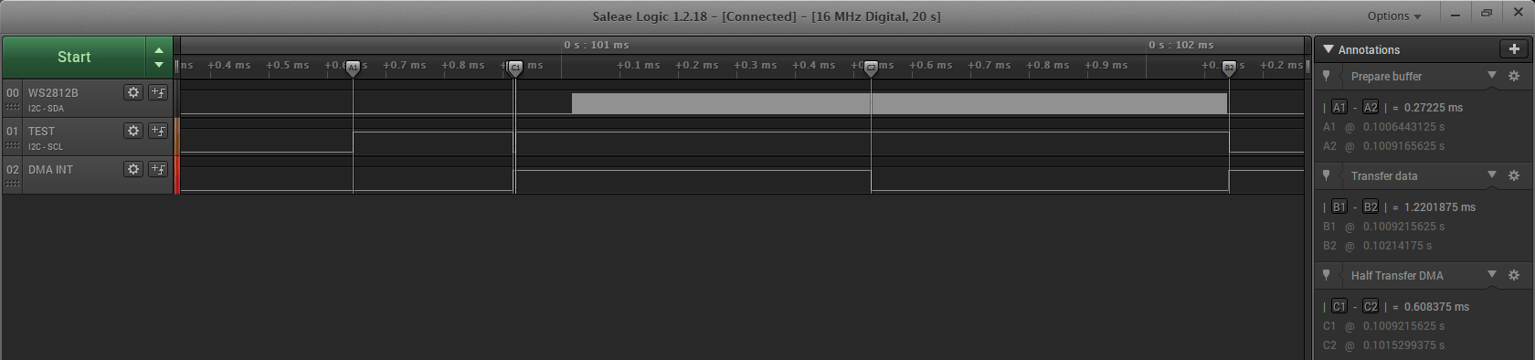
The first two will be perfect. After all, you can create a small data buffer, run cyclic DMA, and when the half-transfer interrupt occurs, replace the first half of the buffer. Brilliant! Note also that preparing a complete buffer takes significantly less time than sending half of that buffer. The MCU should manage it with a finger in… GND 😉
Important: The function that starts the SPI transfer via DMA takes the size of the buffer holding the data, not the total amount of data you want to send! Starting DMA in circular buffer mode will keep sending data until you stop it manually. Therefore, in the half-transfer and full-transfer interrupts, you need to count how many LEDs’ data have already been sent and stop the DMA after the last batch.
I’ll shorten the data buffer to 48 bytes, i.e., it will fit the data for two LEDs. This will pack nicely. The operating scheme is as follows:
- Load 2*24 bytes of the reset signal and start cyclic DMA transmission.
- Half-transfer trigger – load the next 24 bytes into the first half of the buffer.
- Full-transfer trigger – data of the first LED into the second half of the buffer
- Half-transfer trigger – data of the second (even) LED into the first half of the buffer
- Full-transfer trigger – data of the third (odd) LED into the second half of the buffer
- Repeat 4 and 5 until all LEDs have been sent
- Enjoy the effect
A fun fact. The HAL library is written in such a way that the callbacks of individual DMA interrupts are declared in it with the weak symbol. This means that you can override them in your source files, but they must have the same name, arguments, and return type. ST wrote HAL so that you don’t have to worry about enabling the appropriate DMA interrupts via bits and registers. If we declare our own functions appropriate to the interrupt we need, inside the HAL_SPI_Transmit_DM function this will be detected and the library will activate the appropriate interrupts for us. You don’t have to worry about anything. Nice, isn’t it? The only thing to remember is to enable the global DMA interrupt in Cube and assign it a priority. Moving on to my code:
void WS2812B_Refresh()
{
	CurrentLed = 0;
	ResetSignal = 0;

	for(uint8_t i = 0; i < 48; i++)
		buffer[i] = 0x00;

	HAL_SPI_Transmit_DMA(hspi_ws2812b, buffer, 48); // Additional 3 for reset signal
	while(HAL_DMA_STATE_READY != HAL_DMA_GetState(hspi_ws2812b->hdmatx));
}

void HAL_SPI_TxHalfCpltCallback(SPI_HandleTypeDef *hspi)
{
	if(hspi == hspi_ws2812b)
	{
		if(!ResetSignal)
		{
			for(uint8_t k = 0; k < 24; k++) // To 72 impulses of reset
			{
				buffer[k] = 0x00;
			}
			ResetSignal = 1; // End reset signal
		}
		else // LEDs Odd 1,3,5,7...
		{
			if(CurrentLed > WS2812B_LEDS)
			{
				HAL_SPI_DMAStop(hspi_ws2812b);
			}
			else
			{
				uint8_t j = 0;
				//GREEN
				for(int8_t k=7; k>=0; k--)
				{
					if((ws2812b_array[CurrentLed].green & (1<<k)) == 0)
						buffer[j] = zero;
					else
						buffer[j] = one;
					j++;
				}

				//RED
				for(int8_t k=7; k>=0; k--)
				{
					if((ws2812b_array[CurrentLed].red & (1<<k)) == 0)
						buffer[j] = zero;
					else
						buffer[j] = one;
					j++;
				}

				//BLUE
				for(int8_t k=7; k>=0; k--)
				{
					if((ws2812b_array[CurrentLed].blue & (1<<k)) == 0)
						buffer[j] = zero;
					else
						buffer[j] = one;
					j++;
				}
				CurrentLed++;
			}
		}
	}
}

void HAL_SPI_TxCpltCallback(SPI_HandleTypeDef *hspi)
{
	if(hspi == hspi_ws2812b)
	{
		if(CurrentLed > WS2812B_LEDS)
		{
			HAL_SPI_DMAStop(hspi_ws2812b);
		}
		else
		{
			// Even LEDs 0,2,0
			uint8_t j = 24;
			//GREEN
			for(int8_t k=7; k>=0; k--)
			{
				if((ws2812b_array[CurrentLed].green & (1<<k)) == 0)
					buffer[j] = zero;
				else
					buffer[j] = one;
				j++;
			}

			//RED
			for(int8_t k=7; k>=0; k--)
			{
				if((ws2812b_array[CurrentLed].red & (1<<k)) == 0)
					buffer[j] = zero;
				else
					buffer[j] = one;
				j++;
			}

			//BLUE
			for(int8_t k=7; k>=0; k--)
			{
				if((ws2812b_array[CurrentLed].blue & (1<<k)) == 0)
					buffer[j] = zero;
				else
					buffer[j] = one;
				j++;
			}
			CurrentLed++;
		}
	}
}
Results of the reduced buffer
What do the waveform and the individual stages of preparing and sending data from the buffer look like now?
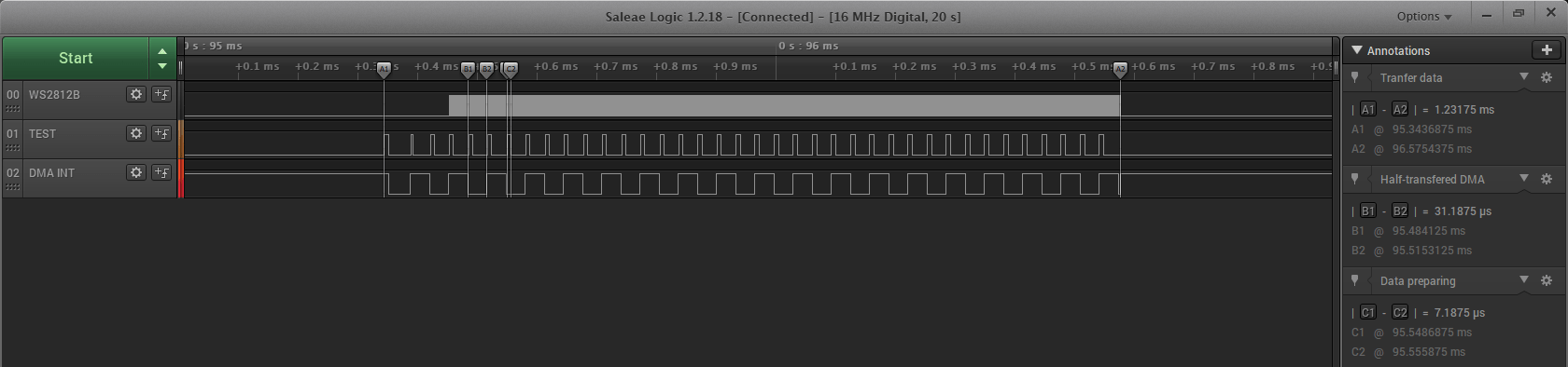
The total frame transfer time has not changed significantly. Overall, the transfer increased slightly to 1.23 ms. The time required to send half the buffer (24 bytes) via DMA is 31 µs. Very little. Preparing the next batch of 24 bytes of data takes the MCU only 7 µs. That gives 26 µs of CPU time saved per LED, which it can use for something else. Too little? With 100 LEDs that’s 2.6 ms, while with 1000 we have 26 ms of CPU time. The transfer time differences compared to sending one large buffer are small. But what RAM savings! 912 bytes for a full buffer vs. 48 bytes for chunking—and that’s with just 35 LEDs. Increasing the number of lit points in the chain and sticking with the concept of one big buffer causes the buffer size to grow drastically. 100 LEDs is already about 2.4 kB of data. Meanwhile, using a small buffer and half-transfer DMA interrupts, the buffer remains unchanged! Beautiful.
Summary
WS2812B LEDs are great. With a really minimal number of connections, we can set EVERY LED individually. It’s true there’s no actual addressing of the LEDs here, but you can easily move through them in the buffer. We achieve this effect without multiplexing and without separating color channels. Control may seem troublesome, but skillful use of standard interfaces in STM32 allows for trouble-free control of really long chains. The use of SPI presented in this post has one basic drawback. The pin responsible for the SCK of the serial interface is unused and can’t be used for anything else (at least not that I know of). When creating a packed and complicated project, that pin could come in handy. Fortunately, most projects I know using flashy combinations on LEDs don’t have too many circuits connected to the MCU. Go ahead and create your own! In two weeks I’ll present some ready-made lighting effects that will certainly come in handy on the Christmas tree.
Thank you for reading this post. If you like this topic, let me know in the comments. I’d also be grateful for suggestions of topics you’d like me to cover.
The code is, as usual, available on my GitHub: link
If you noticed any error, disagree with something, would like to add something important, or simply think you’d like to discuss this topic, write a comment. Remember that the discussion should be polite and in accordance with the rules of the Polish language.
This article is part of the series:
Podobne artykuły





0 Comments