A new board has hit the market! It is a newer and more powerful version of everyone’s favorite low-cost platform with STM32F103, i.e., the BluePill. The new PCB is unofficially called BlackPill due to its black color scheme. The predecessor also owed its name to its color.
Two versions of BlackPill
The new boards can be found in two variants:
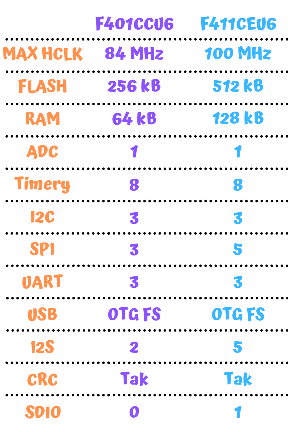
- with STM32F401CCU6
- with STM32F411CEU6
They differ mainly in the amount of FLASH and RAM. A full comparison is in the table below.
Both boards can be purchased in my store. As of the day of writing this post, I am the first store in Poland to have BlackPills 🙂
Additionally, the F411 features the SDIO interface, which is very interesting. It lets you handle SD cards very easily.
Compared to the old BluePill you can find several differences on the board itself. Let’s start with the top layer.
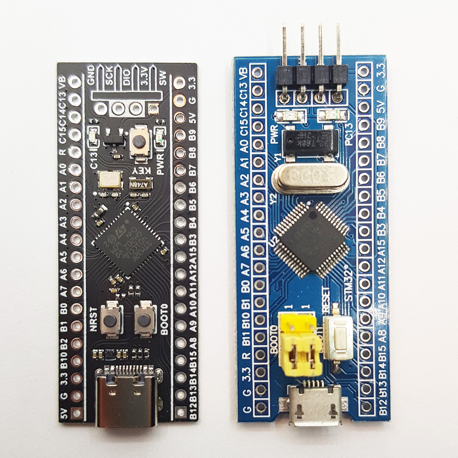
As you can see, the concept of the whole board is similar. The USB port, SWD pins, and board connectors are in the same place.
Unfortunately… The pinouts on the header connectors are not identical. Keep this in mind in projects where you’d like to swap the boards without any modification. You risk a short circuit, for example due to the GND pin being changed to 5V next to the USB connector!
Basically, you need to pay attention to all the pins on the left side of the board (in the photo). Some are swapped, some shifted by one position. The manufacturer could have already done some gymnastics and made a pin-compatible board… It certainly was possible.
However, at first glance the USB connector stands out. On the BlackPill we have USB‑C. Is that a good choice? In my opinion, yes! Electronics must move forward, and I’m glad that first phones, and now other electronics are being equipped with USB‑C. If you don’t have a USB‑C cable yet, sooner or later you’ll need one.
You can buy such a cable in my store. However, you need to keep in mind what kind of cable you’re buying. Not every cheap cable has data lines. Fortunately, mine do 🙂
Going up, we find differences in handling the microcontroller’s control pins. The BOOT0 and BOOT1 pins on the BluePill were on jumpers. Now not only is only BOOT0 available, but it’s also on a button. Why?
BOOT1 on the F4 was moved and integrated with pin PB2. To enter the bootloader, the microcontroller samples both pins right after reset. Therefore, there is no need to permanently tie these pins to constantly enter the built‑in bootloader. This solution saved a lot of space for additional passive components needed for USB operation and the 3.3 V regulator.
In the very center we of course have the microcontroller. Just like on the BluePill, it is a 48‑pin version but without protruding leads, which makes it take up slightly less space. The difference in the MCU itself is obvious. Instead of the STM32F103 we have the STM32F401 or STM32F411 here.
You’ll find more differences in the resonators/oscillators. On the BlackPill the Chinese decided to mount really small oscillators. Interestingly, the HSE oscillator is 25 MHz rather than 8 MHz as before. The second is the classic watch LSE at 32,768 Hz.
Thanks to the use of such tiny oscillators, apart from LEDs the remaining part of the PCB also fits a user button. The BluePill unfortunately didn’t have that, and it would often come in handy.
Let’s move to the bottom side of the boards.
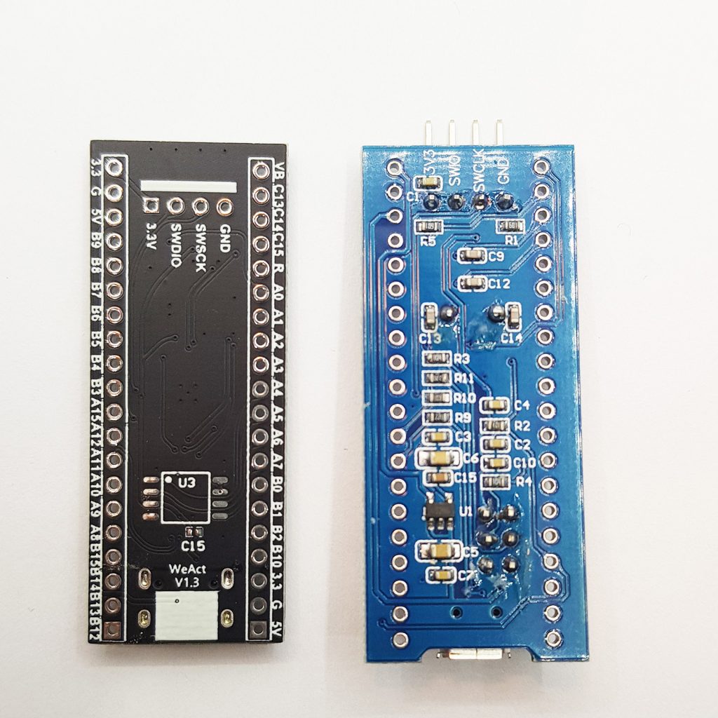
On this side the difference is big. On the BlackPill you won’t find a single component. The manufacturer opted for single‑sided assembly, which certainly reduced production costs.
BluePill has many necessary passives required for operation and a 3.3 V regulator.
I’d like to draw attention to component U3 on the BlackPill board. This is a footprint for SPI Flash memory. Someone came up with a great idea, because with F4 family microcontrollers you can build a pretty decent device with a display or data logging. Flash memory will certainly come in handy for graphics. I like this use of the bottom side of the PCB.
You can preview the connection of this memory in the schematic. Thanks to one of the members of our wonderful STM32 Polska group, we have the BlackPill schematic translated from Chinese to English. Thank you!
First attempt
It would be good to check whether this board works at all. In the article about the BluePill I complained a bit that you can often find counterfeit ST chips in them. I haven’t heard of F4 counterfeits yet, so maybe there’s a chance they’ll all work correctly.
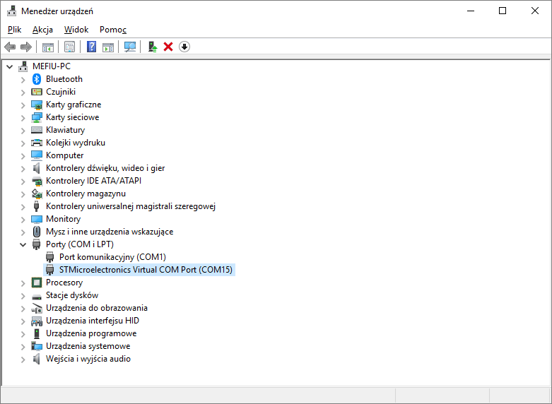
Connecting to USB causes the system to recognize a VCOM device. That’s good 🙂
Since it enumerates as a serial port, maybe it prints something at startup?
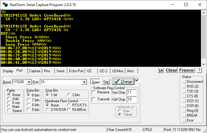
As you can see, the board introduces itself, also giving the symbol of the 3.3 V regulator in case you ever burn it. We also have the option to use the KEY button on the board. The program recognizes a short, double, and long press. Unfortunately, there’s no description of what they do, so I have to check.
Each of these presses changes the way the built‑in LED blinks. Short or long blinking, or breathing. A simple demo.
I bet the preloaded firmware contains an Arduino‑compatible bootloader. Everything has to have such a bootloader now. Unfortunately, I didn’t check that, because that’s not what this blog is about 🙂 However, I did dump this firmware. You can download it here.
But every STM32 has its own bootloader that we can access through a fairly large number of interfaces. I’ll check what it’s like to connect over USB.
I mentioned earlier that BOOT1 has taken over pin PB2. Let’s see how to set these pins to enter the bootloader.
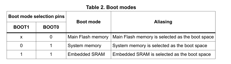

We need to enter System memory, so BOOT0 has to be tied to power, and BOOT1 to ground. First, let me check the schematic to see whether something isn’t selected by default.By default BOOT0 is pulled to ground, but via the button you can easily tie it to one. BOOT1 is pulled down to ground, so that’s perfect. After reset it’s enough to briefly hold the BOOT0 button to put the chip into the bootloader.
I tried, but the chip wouldn’t enter DFU… Only placing a jumper to ground on PB2 helped. Perhaps that pull‑down is too weak, or something else affects it.
When the STM32 enters DFU, you can connect to it with the interface selected in STM32CubeProgrammer. I chose USB. It connected successfully!
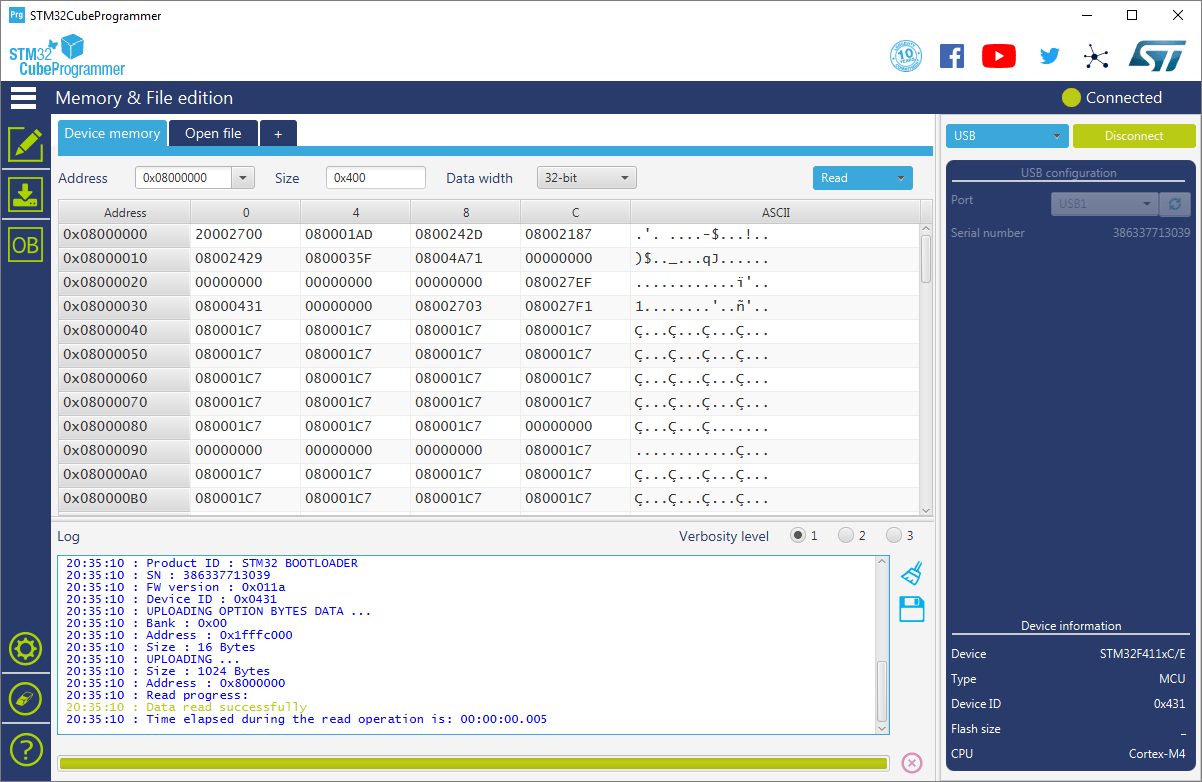
At this point I dumped the factory firmware. When connected via USB, there’s no information about the size of FLASH that our microcontroller has. I wonder why that is… I’ll try with an ST‑Link.
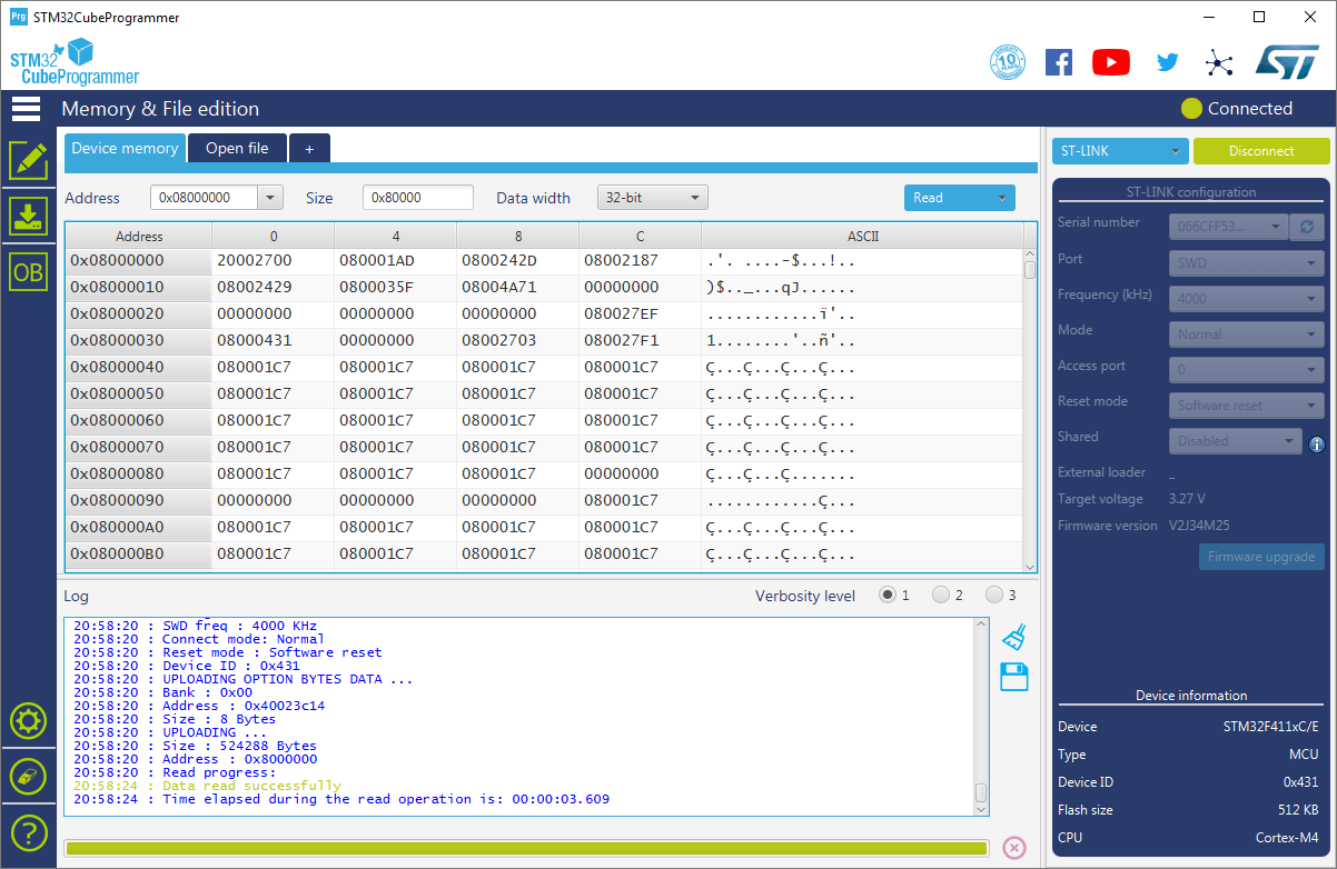
ST‑Link has detected the FLASH size and it is 512 kB for the STM32F411CE.
Test programming
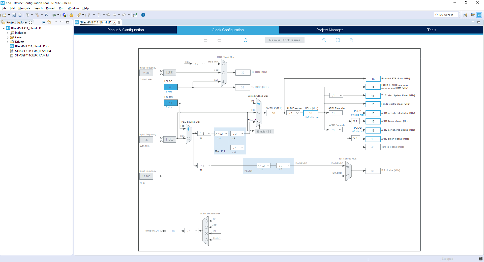
It would be good to create a quick project in Cube and blink the LED that is on the PCB. I’ll use STM32CubeIDE v1.1.0 together with the HAL F4 v1.24.2 libraries.
The clock tab looks very simple. We are not dealing with a complex tree, which in my opinion is a plus for a beginner.
In the main view on the left you will of course find expandable trees with peripherals. Compared to the BluePill there are a few more here.
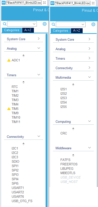
We can see what I listed earlier in the comparison table. A ton of interesting interfaces, including SDIO. In addition, we have something called Middleware. These are libraries prepared by ST that can be easily added to a project. Here you’ll find, among others, FATFS for SD cards and USB support. Super useful libraries.
Alright, but I just wanted to blink an LED 🙂 Allow me to skip the whole matter of programming a blinking LED. You can find that, for example, in my e‑book, which you will receive by joining my newsletter (content in Polish).
Compared to the BluePill there is no Flash lock here. You don’t need to change anything with a programmer or erase anything to start working with the board. Everything works right away. Great!
Summary
I really liked this board. It was my first try, but it’s a much better experience than with the BluePill. Fingers crossed that this mini‑euphoria remains. More posts using the new boards will probably appear.
The only downside is combining an ST‑Link and using a breadboard. I can’t get around that. You can use DFU to avoid connecting an ST‑Link, but then you won’t have a debugger.
You can buy the boards in my store. I will be incredibly grateful for your purchase and support of my work!
Podobne artykuły


0 Comments