I remember how many years ago multiplexing an LED matrix was a nightmare for me. Geez… how badly I went through it. From today’s perspective I don’t understand my past self at all. It really isn’t as difficult as it seemed to me back then. Today it’s even simpler! We have specialized multiplexing chips designed for LED displays, and that’s beautiful. Let’s get cracking!
Complete series of posts:
Never again multiplexing on GPIO! MAX7219 in action part 1
Never again multiplexing on GPIO! MAX7219 in action part 2
Never again multiplexing on GPIO! MAX7219 in action part 3
MAX7219
One such chip is the MAX7129 (
MAX7219-MAX7221 Datasheet.pdf
) which I’m discussing today. It’s a chip that can control LED displays with a common cathode. It can handle 8 seven-segment displays + dot, i.e. a total of 64 LEDs. They don’t necessarily have to be segment displays. They can also be 8×8 matrices, as you’ll see later. Interestingly, it has a built-in BCD decoder that can make working with the chip easier. It uses built-in RAM to remember what to display.
We can talk to the chip via the SPI interface. The chip supports cascading, which allows connecting the ICs into long chains. This is a feature that enables large LED matrix sizes.
Manufacturers in the Far East produce modules with the MAX7219 in versions with seven-segment displays and with 8×8 matrices.
Schematic and Cube
The modules supplied by Chinese manufacturers are very simple to connect. The board has pins on two sides. One side is the input, the other is the output for cascading. Since we can’t read anything from the chip, the SPI connection and configuration will be in Master Transmit Only mode. Today an STM32L476RG mounted on a Nucleo board landed on my bench.

The connection schematic looks like this:
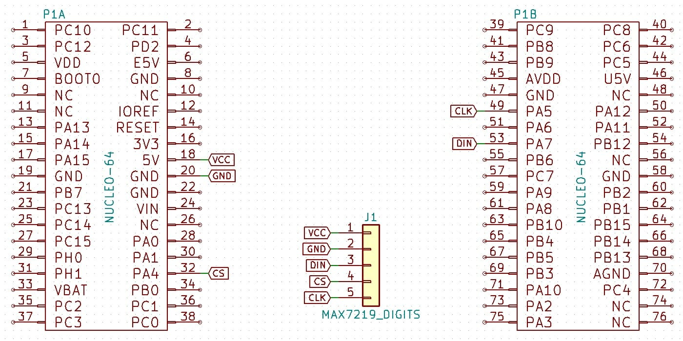
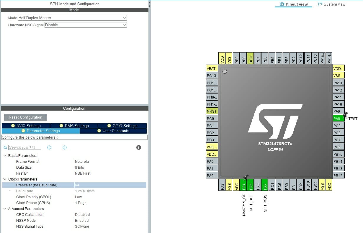
As usual, I set the MCU main clock to as much as the factory allows – 80 MHz. It’s quite convenient for testing single chips. The SPI prescaler will initially have a value of 64, which results in 1.25 MHz on the serial interface clock. The CS pin can be configured as Software or Hardware. We’ll handle both cases.
Coding, coding, coding!
MAX7219 provides several configuration registers.
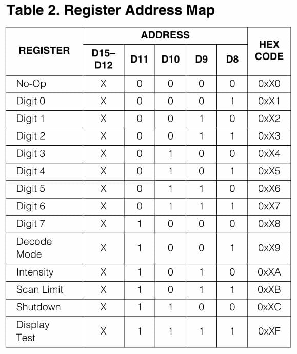
What can we do with them? Besides the obvious Digit X registers, the others allow you to:
- Enter Shutdown mode – turn off the oscillator, blank the LEDs
- Change LED brightness by setting the duty cycle of the applied signal
- Set the scan limit – limit displaying up to the i-th digit
- Enable display test – all LEDs light at maximum brightness
All these maneuvers are handled in my library via convenient enums.
MAX7219_STATUS MAX7219_SetDecodeMode(uint8_t DeviceNumber, MAX7219_DecodeMode DecodeMode);
MAX7219_STATUS MAX7219_SetIntensity(uint8_t DeviceNumber, uint8_t Intensity);
MAX7219_STATUS MAX7219_SetScanLimit(uint8_t DeviceNumber, MAX7219_ScanLimit Limit);
MAX7219_STATUS MAX7219_Shutdown(uint8_t DeviceNumber, MAX7219_ShutdownMode Shutdown);
MAX7219_STATUS MAX7219_SetDisplayTest(uint8_t DeviceNumber, MAX7219_TestMode Enable);
The basic configuration is performed during initialization, to which, as is typical for me, you need to pass a pointer to SPI.
MAX7219_STATUS MAX7219_Init(SPI_HandleTypeDef *hspi);
Alright, but there’s also a ‘register’ called No-Op. As the name suggests, sending this to the chip causes no operation. What is it for? It’s used for cascade mode, where data applied to DIN are then forwarded to DOUT.
MAX7219 works like a shift register. Data written into it are latched when the CS signal returns to a high state. Then the last 16 bits that ended up in the register are the ones that determine the operation performed. I’ll describe this in more detail when we get to the cascade.
Setting a digit for a single chip is easy. You just need to send the selected value to the appropriate register. Keep in mind which decode setting is selected. If the MAX7219 is to decode BCD into the appropriate segments by itself, it suffices to send a number in the range 0÷9.
However, I encourage you not to use the BCD decoder. Why? Because you can define more characters on the display. I prepared a list of letters that came to my mind and can be realized on 7-segments. Nothing stands in the way of adding your own.
To set individual digits, use the function
MAX7219_STATUS MAX7219_SetDigit(uint8_t DeviceNumber, uint8_t Digit, uint8_t Value, uint8_t Dot);
Note that the numbering of Digit kind of starts from the end. Digit zero is on the right, and the seventh on the left. That’s not very natural for us, but the display is physically connected that way to the chip’s pins.
Printing
But is sending single characters convenient? Not really. It’s much better to use something like printf. For this purpose I created a few helper functions.
MAX7219_STATUS MAX7219_PutString(int Start, char *String);
MAX7219_STATUS MAX7219_PutStringRightAdjust(char *String);
MAX7219_STATUS MAX7219_PutStringLeftAdjust(char *String);
MAX7219_STATUS MAX7219_PutStringCenterAdjust(char *String);
The first one writes a string starting from position Start. At this point I fixed the inhuman digit layout across the display and position zero is on the left. The function accepts all ASCII characters that I defined under their real codes. It’s therefore easy to just write whatever you want. Characters that are not in the defined table are skipped.
Alright, but what about the dot?! On seven-segment displays it’s an integral part of the digit! That’s right, and I prepared for that objection. Printing handles dots. When a dot appears as a character in the string, it is appended to the digit. Check yourself how it works.
The other 3 functions are a little gimmick. They are intended to align the input string to the right, to the left, and to center it. Just like in text editors.
All these functions support cascading, which I’ll discuss in the next part of the post.
Operation
Another quick look at how it works. Let’s first check how long it takes to display all eight digits.
SCK 1.25 MHz
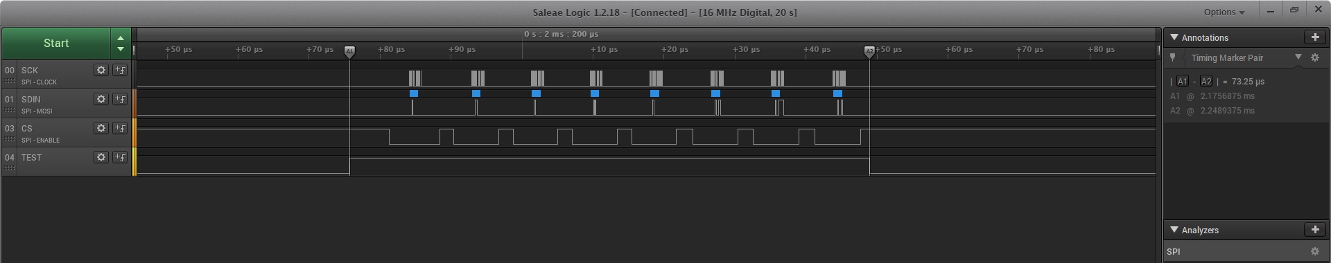
SCK 2.5 MHz
SCK 5 MHz
SCK 10 MHz
The results are as follows:
- 1.25 MHz – 176 µs
- 2.5 MHz – 118 µs
- 5 MHz – 88 µs
- 10 MHz – 73 µs
Unfortunately, the chip doesn’t cooperate when it comes to overclocking. Above 10 MHz it starts showing garbage, so the value in the documentation really is the maximum.
Summary
As you can see, one may consider multiplexing on GPIO a thing of the past. Who would want to do it manually now? Perhaps in applications where the unit price of the device has to be pushed to the absolute limit. However, even then you should consider whether saving on the chip will really be more beneficial than saving the time needed to implement multiplexing.
In the next part I will discuss building a cascade of MAX7219 chips.
If you liked the seven-segment display module described today, you can buy it in my store.
The full project together with the library can be found as usual on my GitHub: link
If you noticed any error, disagree with something, would like to add something important, or simply feel like discussing the topic, write a comment. Remember that the discussion should be polite and in accordance with the rules of the Polish language.
Podobne artykuły


0 Comments