Many people rave about the beauty of OLED displays because there’s something amazing about them. Infinite contrast and high refresh rate are incredible advantages of this technology. On the market you can find plenty of tiny monochrome OLEDs in sizes from about 0.49″ up to roughly 4″. Their price has dropped significantly in recent years, making them wildly popular. Let’s see how to tame an SSD1306 OLED using an STM32!
OLED technology
Probably the most important feature of this technology is the fact that every pixel is an individual organic light-emitting diode. This means there’s no need for backlighting the matrix, so the display is very thin and essentially made of glass alone. Thanks to this, these displays can theoretically achieve infinite contrast. In short – a black pixel emits nothing, and white is white.
The lack of power-hungry backlighting means energy efficiency, as this is the component that consumes the most power in classic LCD displays.
But nothing comes for free… Because the pixels are diodes, they can suffer from burn-in. Over time, diodes lose brightness. Depending on the color, the drop to half the initial brightness may take about 20–100 thousand hours. This is stated in every datasheet. That seems like a large value, and it actually is. Unfortunately, the human eye can perceive relative brightness differences after just a few percent drop. Hence we see burn-in in areas where the OLED shows a static image. You’ll notice this in a year or two (if you don’t already) on early OLED TVs, and it will be quite a big problem in the first models.
A very good article about OLEDs was once written by a colleague of mine. I invite you to read it (link).
SSD1306 OLED controller
We never have access to a bare matrix. There’s always some controller in between. This is the case with alphanumeric displays (HD44780), TFTs, and OLEDs. The controller’s job is to receive instructions from the host on how to set the pixels on the matrix. They often feature additional built-in functions.
A popular manufacturer of OLED display controllers is Solomon Systech Limited. They produce very good, popular controllers marked SSD. They offer a dozen or so chips capable of driving OLED matrices. They differ in the sizes of supported matrices, interfaces, or available grayscale levels. For those interested, see the brochure –
SSD_OLED_IC_Catalog
. Undoubtedly, the most popular on the market is the SSD1306. It’s relatively simple. It supports matrices up to 128×64 pixels. It has a 256-step brightness scale and note, this is not grayscale. It simply dims/brightens the entire matrix. It has built-in RAM for the displayed image. You can talk to it via an 8-bit parallel interface, I²C, or SPI (3/4-wire), with the parallel interface rarely implemented on Chinese modules. And that’s good because I believe I²C and SPI are fast enough. An important feature is the built-in voltage converter, since OLED panels require about 12 V to operate. Thanks to this converter you don’t have to worry about it, although supposedly they can whine. Luckily, I’ve never had one do that.
This controller has a few built-in effects:
-
- Screen scrolling, e.g. for a simple screensaver – even pixel wear.
- Fade Out and Blinking function
- Zoom
You’ll find more valuable information in the chip’s datasheet –
SSD1306 Datasheet
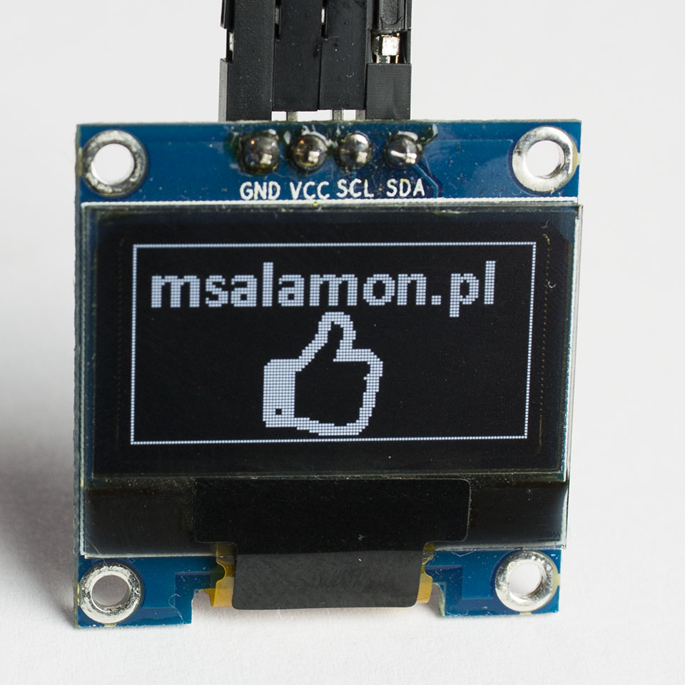
. I will focus on a display based on this controller. It will be 0.96″.
Control
Chinese modules offer two interfaces – I²C and SPI. Communication is split into commands and data. The choice of the type of information transmitted over I²C is made by writing to the appropriate register (0x00 for data and 0x40 for commands). In SPI it’s a bit different because you can choose 3- or 4-wire communication. With four wires, in addition to the standard SPI signals, there is also a D/C signal that determines what is being sent to the display. If 3-wire mode is selected, you need to send an extra bit at the beginning of each byte. This makes the communication 9-bit. So, shall we? Let’s get cracking!
Library
The code provides several definitions you can change, such as:
- interface selection and its settings, e.g. the I2C address
- matrix resolution
- selection of graphic functions offered by the display controller
The rest of the control is done through appropriate functions. Image creation is based on an RAM buffer in the MCU. It contains information about each pixel – the so-called frame. This is a monochrome display, so the entire buffer occupies only 1 kB of RAM. That’s not much for an STM32, and using such a buffer offers great convenience. Thanks to it, it’s easy to implement image overlaying (the transparency argument).
The basic function is initialization. Depending on the interface, it takes as an argument a pointer to the appropriate I²C or SPI structure. Note. This function sets, among other things, matrix size, COM voltage, and drawing directions, which can differ especially with other resolutions and sizes. Make sure you have the right ones and, if necessary, change them to those recommended by your display’s manufacturer. Smaller resolutions may have a different pixel-to-memory organization. However, for most cases, these settings should be correct.
Four configuration functions allow you to:
- Enable/disable pixels.
- Invert colors
- Rotate the display by 180°
- Set contrast – 256-step display brightness
Next, the most important display functions.
void SSD1306_DrawPixel(int16_t x, int16_t y, uint8_t Color);
Drawing a single pixel in the RAM buffer. This function draws a pixel with the given coordinates and color in RAM. It is not sent to the display. This allows you to prepare all graphics before they are sent to the OLED’s RAM.
void SSD1306_Clear(uint8_t Color);
Fill the RAM buffer with the selected color. Only WHITE and BLACK are available. Any other value will be ignored. It’s used to clear the frame contents.
void SSD1306_Display(void);
Send the entire buffer to the display’s RAM. Only when this function is called is the previously prepared buffer sent to the display and the final image appears on the matrix.
void SSD1306_Bitmap(uint8_t *bitmap);
This function is similar to SSD1306_Display, except that we can send an image that is outside the buffer, e.g. in Flash memory. It must be the same size as the matrix. Otherwise some garbage from memory will be sent or a HardFault will occur.
Next, I implemented the graphics functions offered by the controller. There is content scrolling in different directions.
void SSD1306_StartScrollRight(uint8_t StartPage, uint8_t EndPage, scroll_horizontal_speed Speed);
void SSD1306_StartScrollLeft(uint8_t StartPage, uint8_t EndPage, scroll_horizontal_speed Speed);
void SSD1306_StartScrollRightUp(uint8_t StartPage, uint8_t EndPage, scroll_horizontal_speed HorizontalSpeed, uint8_t VerticalOffset);
void SSD1306_StartScrollLeftUp(uint8_t StartPage, uint8_t EndPage, scroll_horizontal_speed HorizontalSpeed, uint8_t VerticalOffset);
void SSD1306_StopScroll(void);
Arguments of type scroll_horizontal_speed decide how many frames apart the animation advances. This is not the number of frames you send to the controller. These are the controller’s refresh frames, based, among other things, on Display Clock and Multiplex Ratio values provided during initialization. For convenience, they are in enumerated form. I encourage you to experiment with these functions.
typedef enum
{
	SCROLL_EVERY_5_FRAMES,
	SCROLL_EVERY_64_FRAMES,
	SCROLL_EVERY_128_FRAMES,
	SCROLL_EVERY_256_FRAMES,
	SCROLL_EVERY_3_FRAMES,
	SCROLL_EVERY_4_FRAMES,
	SCROLL_EVERY_25_FRAMES,
	SCROLL_EVERY_2_FRAMES
} scroll_horizontal_speed;
The last section is the “advanced” graphic commands. The first is Fade Out.
void SSD1306_StartFadeOut(uint8_t Interval);
It gradually dims the display, i.e. decreases the contrast. The change goes from the given Interval down to zero and remains there until canceled.
A similar effect is blinking.
void SSD1306_StartBlinking(uint8_t Interval);
The effect is similar to Fade Out, except that the display returns to the Interval value and “blinks” in a loop.
After dimming or setting blinking, the display does not return to the “normal” state. You need to pull it out with
void SSD1306_StopFadeOutOrBlinking(void);
The last, most pointless function for me is Zoom In.
void SSD1306_ZoomIn(uint8_t Zoom);
It only works with the full possible matrix, i.e. 128×64, and the idea is that the top half of the display (128×32) is stretched downwards. See how it works for yourself. Will it be useful?

Graphics library
The graphics library I use is based on various examples from the Internet. It can be used with both STM32 and AVR. It requires passing three values to work correctly. These are the function that draws a single pixel and the display dimensions in pixels.
#define GFX_DrawPixel(x,y,color) SSD1306_DrawPixel(x,y,color)
#define WIDTH SSD1306_LCDWIDTH
#define HEIGHT SSD1306_LCDHEIGHT
In my example, the library will draw in the RAM buffer because that’s what the pixel function does. To send this to the OLED controller, you’ll need to use SSD1306_Display().
I also included a few switches to decide which drawing functions will be needed. You can save some Flash space by skipping compilation of unnecessary things. What gets compiled is determined by USING_XXX-style switches (#define). Setting zero removes the given function, while one adds it to the code. Some functions require others, and I added a small “automaton” to handle that. Available are:
- Strings in various sizes
- Images
- Rotated images in 1° steps – a very primitive function that can leave empty pixels during rotation
- Drawing geometric shapes (squares, circles, triangles – empty, filled, rounded or not)
I encourage you to play with the library and report bugs or modification proposals to me. Now I’ll move on to the main part of the post.
I²C
I’ll start with I²C. With an STM32 I only need two wires for this interface, so it’s a tempting option for default use. The SSD1306 datasheet says that the maximum supported I²C clock is 400 kHz. For today’s tests I’ll use a Nucleo with STM32L476RG on board. It supports I²C communication in Standard Mode (100 bit/s), Fast Mode (400 bit/s), and Fast Mode Plus (1 Mbit/s). I’ll try to overclock the SSD1306 controller’s I²C clock, why not! Let’s see what happens.
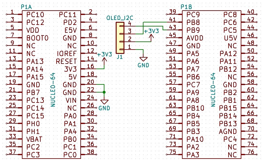
Since I used a ready-made module with the display, the schematic to connect it to I2C1 is trivially simple.
First I’ll test a “safe” clock value – 100 kHz. Cube configuration is trivial.
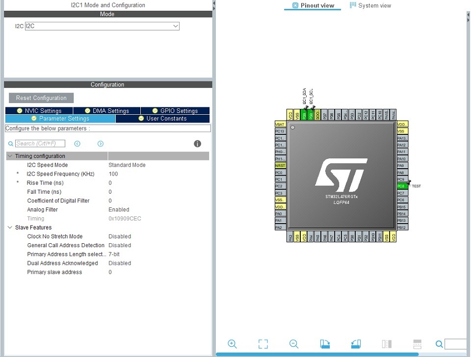
In later steps I’ll change the speed via the I2C Speed Mode menu, but I won’t show that on screenshots. Sending a complete frame at an I²C clock frequency of 100 kHz looks like this:
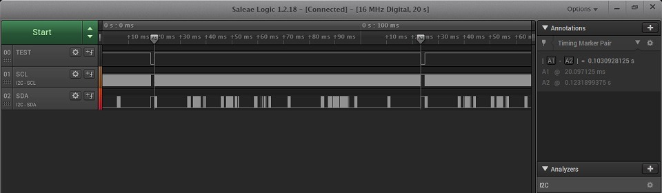
The time to send all pixels is about 103 ms. That’s quite a lot given that sending frame after frame yields only 10 frames per second with 100% MCU load. I’ll increase the speed a bit.
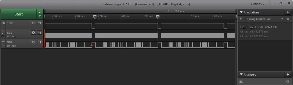
It’s definitely better. 27.4 ms is already a nice value that gives about 36 frames per second. Even though the SSD1306 datasheet states that the maximum I²C clock frequency can be 400 kHz, I’ll try to overclock communication a bit. The STM32L476RG offers Fast Mode Plus. Here’s the effect.
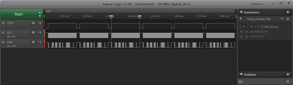
Frame transfer time is only 12.38 ms. This value allows about 80 FPS. That’s quite a lot. Usually such a high FPS isn’t needed, so you can limit it, freeing up CPU for other operations. Speaking of which, can we ease the processor a bit during transfer? Of course! With DMA 🙂 I’ll perform the same operation now by sending the entire buffer via DMA. See how much the CPU usage drops.
100 kHz:
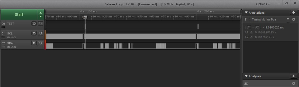
As you can see, the processor is busy for just one millisecond. That’s the time I send over I2C to the display the information that I’m going to send a frame. You can shorten this time a bit.
400 kHz:
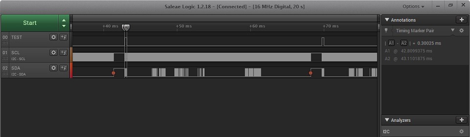
0.3 ms of CPU occupancy at 400 kHz is an excellent result. There’s still 1000 kHz left.
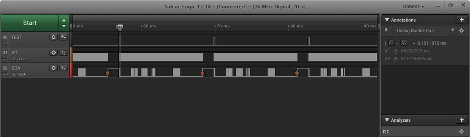
In practice, the STM32L476RG sets the I2C clock to 800 kHz even though 1000 is set in Cube. Hence the “only” twice lower result – 0.15 ms. How fast is that? Very.
If you still don’t know the benefits of using DMA, let me show how many main loops the CPU completes each second while working with the display. These will be results with DMA off and on. The first photos concern blocking transfer, i.e. without DMA.
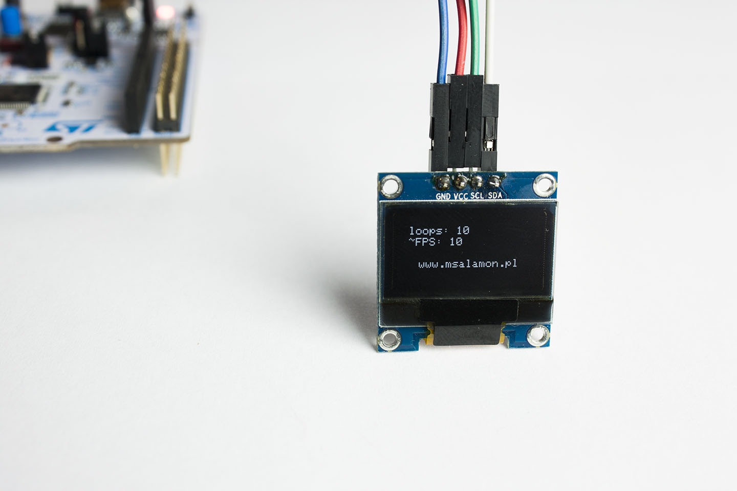
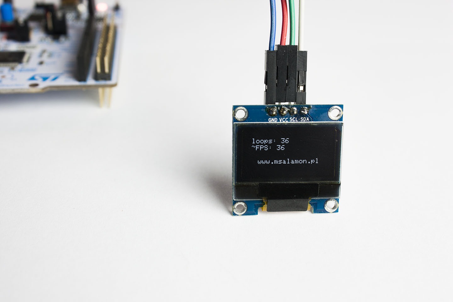
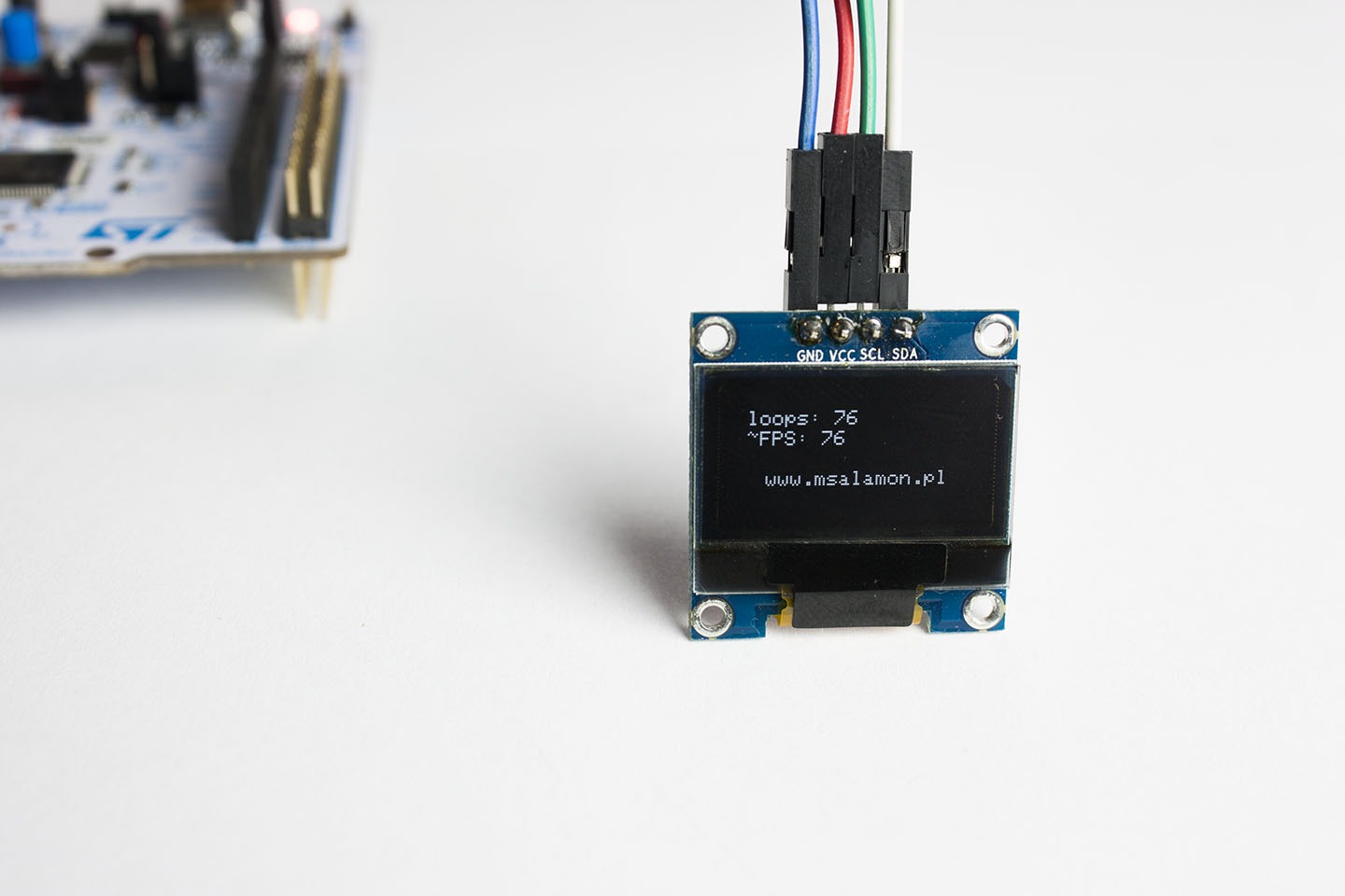
As you can see, the program will execute only as many main loops as frames per second the display is able to show. That’s logical, because the CPU waits until the OLED transfer finishes. Now results with DMA. The transfer of the next frame happens only if the previous transfer has finished. At the same time, the main while loop keeps running all the time.


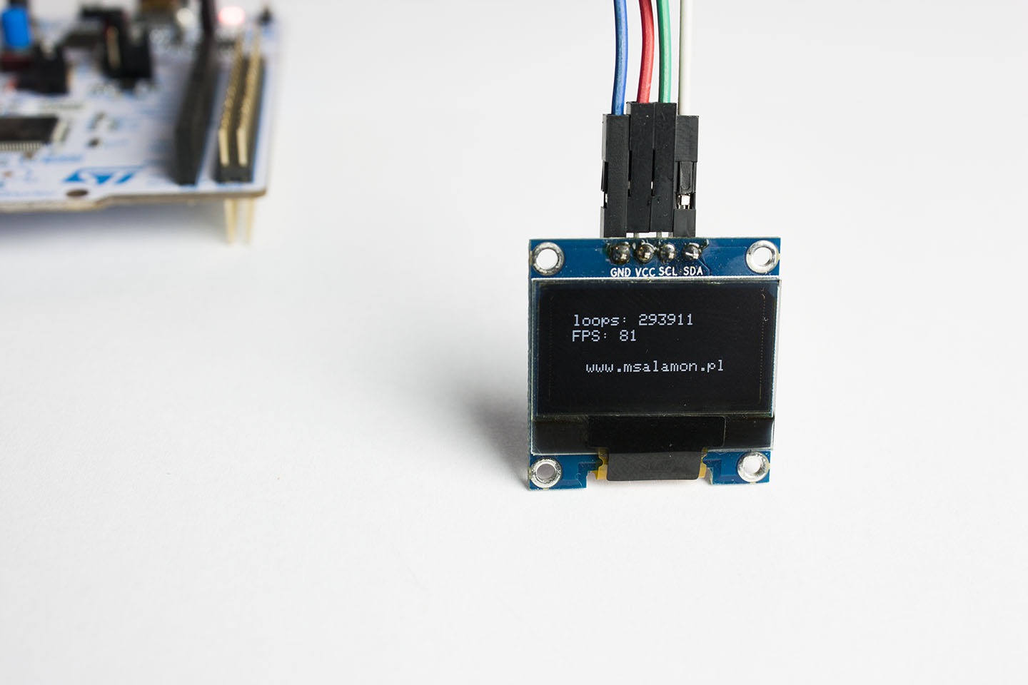
Not only did the FPS count go up, but the program executes about 300 thousand iterations of the while loop per second. While the frame is being transferred by DMA, the CPU is idle and can, for example, receive data from sensors. You can go for double buffering and smoothly prepare data for the display.
Choosing how to handle it – DMA or not – besides the configuration in Cube is done in the library with the #define SSD1306_I2C_DMA_ENABLE definition.
So how does this all look when working with the SPI interface?
SPI
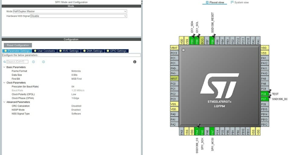
The SSD1306 controller allows the SPI interface to operate with three or four connections. The difference is in connecting the DC pin, which tells the chip whether data or commands are being sent. Communication in 4-wire mode is 8-bit, while 3-wire requires sending 9 bits over SPI each time (one informational bit instead of a dedicated wire). My display does not allow me to test 3-wire mode, so I’ll limit myself to the available four connections. Besides, 9-bit SPI seems rather unnatural… The module I have does not have the MISO pin brought out, but there’s no need to read anything from the display anyway. In such a case, I’ll set SPI to Half-Duplex. SPI + DC equals 4 pins, and there’s also the RESET pin. It’s not mandatory, but if we have free pins in the system, why not use it. It’s enabled conveniently in the library with one ‘define’ – #define SSD1306_RESET_USE. Then this pin should be connected to 3.3 V.
I’ll connect all possible pins to the MCU. The schematic looks like this.
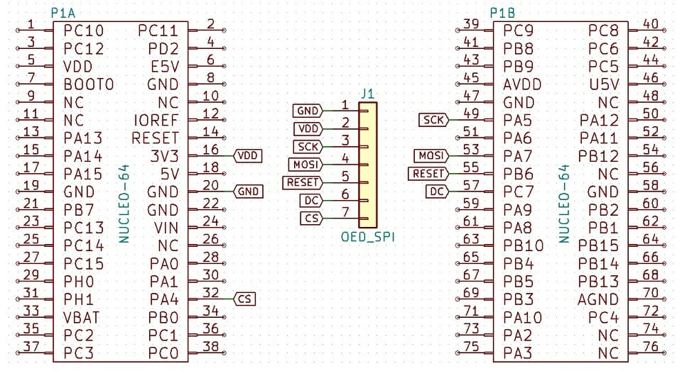
The CS pin strayed a bit from the rest of the group, but there’s a reason for that, which I’ll explain in a moment.
The SSD1306 datasheet says the maximum SPI clock frequency can be 10 MHz. The STM32L476RG runs at 80 MHz, so the prescaler should be set to 8. As with I²C, I can overclock the communication. For SPI, I can raise the SCK line frequency up to 40 MHz. I’ll test it, of course 🙂
Initially, however, I’ll set a reasonably safe value. A prescaler of 64 gives me a clock of ~1.25 MHz. Later it’s enough to just decrease this value. The I²C pins are remnants from the previous mode and are not needed at this point.
Time to see what the analyzer shows. At 1.25 MHz we already get a good result. Sending the whole frame takes 8.25 ms. Definitely better than the maximum I²C frequency, and this is only 12% of the controller’s SPI capability.

For comparison, 5 MHz – 2.07 ms.

And 10 MHz – 1.04 ms. Very fast!

Alright, but what about overclocking? 🙂 I checked what the prescaler allows, i.e. 20 MHz and 40 MHz. As with I²C, the controller didn’t even flinch. I didn’t see any random or missing pixels on the screen. Everything goes smoothly. And the times? Regardless of what the analyzer interprets on MOSI and SCK (16 MHz sampling), the test tells the truth.
Frame transfer at 20 MHz takes just 0.53 ms.

And at 40 MHz… 0.27 ms! What a speed. At such a rate you could skip DMA 🙂

However, remember this is 4 times the maximum value given by the manufacturer. The fact that I managed it on a desk doesn’t mean the display will work flawlessly at 40 MHz in a production environment! It’s better to stick to a maximum of 10 MHz and use DMA.
SPI DMA
Of course, I anticipated this option in the library. Enable DMA the same way as for I²C and use the #define SSD1306_SPI_DMA_ENABLE definition to switch the code to DMA transmission. Unfortunately, that’s not all. As you know, with SPI you also have to control the CS pin. You need to return it to the high state after the DMA transmission is complete. I’m not going to wait for the transfer to finish just to toggle a pin. I didn’t configure DMA to wait like with a regular transfer… There are two approaches that I implemented in the library:
- void HAL_SPI_TxCpltCallback(SPI_HandleTypeDef *hspi) interrupt, i.e. DMA transfer completion. This is a good solution, but remember to enable the interrupt in Cube and place the void SSD1306_DmaEndCallback(SPI_HandleTypeDef *hspi) function in its handler. It has the advantage that any pin can be used as CS.
- The second way is to set the CS pin to hardware control. The MCU can toggle it by itself when needed. Then you can forget about the DMA transfer completion interrupt. The downside is that it has to be a dedicated pin. For SPI1, that’s PA4, hence the “odd” choice from the start. Another downside is that you can’t connect another device to this SPI because the display’s CS will activate whenever you start a transfer on that SPI.
You have to decide what’s right for you. What are the MCU occupancy times with SPI DMA like? 1.25 MHz – 38.37 µs.


5 MHz – 28.81 µs.
10 MHz – 21.81 µs.

It won’t get better than this. At 20 and 40 MHz this time is the same. Most likely the surrounding overhead operations like function returns or HAL SPI handling take much longer than transferring the three commands themselves. Nevertheless, the result is impressive.
What remains is the FPS count and the number of while-loop iterations with DMA. Allow me to skip the photos of the display showing the results. I’ll present them in a table together with I²C.
So which interface to choose?
| CPU time Poll(ms) | FPS Poll | CPU time DMA | FPS DMA | Loops DMA | |
|---|---|---|---|---|---|
| I2C 100 kHz | 109 | 10 | 1.08 ms | 11 | 331655 |
| I2C 400 kHz | 27.4 | 36 | 0.3 ms | 38 | 317300 |
| I2C 800 kHz | 12.38 | 80 | 0.15 ms | 81 | 293911 |
| SPI 1,25 MHz | 8.25 | 104 | 38.37 us | 102 | 2368545 |
| SPI 5 MHz | 2.07 | 285 | 28.81 us | 272 | 1585956 |
| SPI 10 MHz | 1.04 | 403 | 21.81 us | 378 | 1098468 |
| SPI 20 MHz | 0.53 | 507 | 21.81 us | 477 | 691864 |
| SPI 40 MHz | 0.27 | 583 | 21.81 us | 544 | 393303 |
What conclusions can be drawn? Which interface to use in a project? For tinkering or a simple device, it won’t matter much which interface you choose. However, if:
-
- You have few pins, system size doesn’t matter – you can use I²C.
- You have few pins, and the system is time-critical (has many elements and a ton of code executing at once) – take SPI without reset in 3-wire mode. This will require a slight rebuild of the library.
- Any number of pins and any complexity – SPI is definitely the better choice. Unless it’s already taken.
Should you care about the maximum FPS? The only “threat” to animation smoothness is I²C at 100 kHz. Everything else will handle 30 frames for smoothness. It’s also better to programmatically limit FPS to 30 or 60. This isn’t Counter‑Strike.
And DMA? In my opinion, it’s a must have. Life’s too short to wait for the MCU to send data “by hand.” You can really do other things during that time, like data acquisition from all sensors. Operation will be smooth, and the display will please the eye with a consistently high frame rate.
I mentioned double buffering earlier. If you want to send frames at equal time intervals, for example using a timer interrupt, it may happen that the timer triggers the DMA transfer when the MCU is writing some data to the display buffer. Then at least one frame will be corrupted, which a keen eye may notice. You can implement double buffering to solve this. What is it? How to do it? Another time 😉
Summary
OLEDs are great displays. Using them is very enjoyable and I’m eager to use them in my devices. I think I’ve shown the difference between the interfaces well and you’ll choose the right control more consciously.
If you liked OLED displays, you can get them in various variants in my shop.
The project with code is on my GitHub: link
If you noticed any error, disagree with something, would like to add something important, or simply want to discuss this topic, write a comment. Remember that the discussion should be polite and in accordance with the rules of the Polish language.
Podobne artykuły



0 Comments