When working with various graphic displays, you will almost certainly reach a moment when you need some graphics to display. After all, that’s why we pick such a display—to show some icons or other bitmaps on it. Alright, but can we just drop a BMP or JPEG file into our microcontroller? Well, no! So how do we deal with such graphics? What should we use? I’ll show you right away 🙂
Table of contents for the entire SSD1327 OLED series:
Grayscale OLED on SSD1327 part 1
Grayscale OLED on SSD1327 part 2
How to prepare an image for an LCD or TFT display?
Grayscale OLED on SSD1327 part 3
Image representation in a microcontroller
When putting an image into a microcontroller, you need to prepare it beforehand. Usually, such graphics take up quite a bit of space, so we store them in the microcontroller’s Flash memory. To put something into Flash on STM32, it’s enough to add the const specifier to a variable or an array. The compiler will automatically place these variables in the Flash memory area. Simple, right?
Ok, so you’ve probably already figured out that we’ll use variables to store images. Not single variables, but whole arrays. How are they built? We need to think about what an image actually is.
Let’s take a closer look at monochrome images, like the ones used on simple OLED displays. One pixel can have two colors—black or white. To store a single pixel, we really only need one bit. If we want an image for the whole OLED, say 128×64 px, then we need information about 8192 pixels. We would need 8192 variables indicating the color of each pixel.
Not exactly. Since one pixel = one bit, why not pack it? After all, bytes can hold up to 8 bits. That’s exactly what you do! Thanks to this, one 128×64 px image takes “only” 1024 bytes.
Which byte for which pixel?
The organization of pixels in such an array is extremely important. I usually stick to this convention of numbering pixels on displays. This organization is most often forced by the memory organization in the display. It’s easier to do calculations for a single pixel and then send the whole array in bulk without extra tricks.
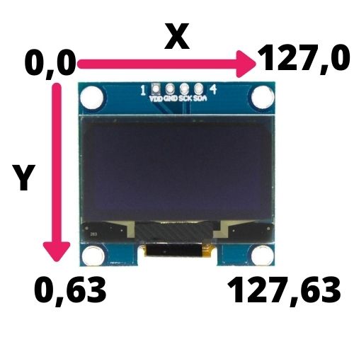
That’s exactly how I number pixels on the display. Now how do we arrange this in an array? The same way as in the buffer for an OLED! The first byte covers pixels in the first row (0,0) to (7,0), the second from (8,0) to (15,0), etc.
The second line, i.e. Y=1, starts at byte (127/8)+1, which is byte no. 16 in the array. Let’s try to write an equation that selects the exact byte in the buffer.
First X. The next byte in the buffer changes every 8 X’s, i.e. image[(x/8)].
Now Y. With each next line we jump forward by (resolution in X / 8) times the number of vertical lines, i.e. [Y*(LCDWIDTH/8)].
Now the depth in X and in Y must be added together. This gives us the byte selection as image[(x/8) + (Y*(LCDWIDTH/8))].
We found the correct byte. Now within that byte we have as many as 8 pixels. Which ones? The X’s! Where will the least significant pixel in the byte be? In the most significant bit position of the byte, i.e. “reversed”. So how do we find the value of that single pixel? Use a mask.
For the zero-th pixel we need the MSB, so the mask will look like this—0x80 (0b10000000). For the second pixel it will be 0x40 (0b01000000). The third 0x20 (0b00100000). Do you see the relationship? The 1 moves to the pixel position counted from the left. So you just shift it by the pixel number. But wait! We have points 8-15. How do we use them?
We’ll need to use the remainder from division, i.e. modulo. We’ll divide X, because that’s where we need this information. By what do we divide? By 8.
In the end, the color of a single pixel is (image[(x/8) + (Y*(LCDWIDTH/8))] & (0x80 >> (X%8)).
That’s a pretty complicated construct. For color displays, where one byte = one color component of a pixel, it’s a bit easier 🙂 Or one pixel = 2 bytes, because a common color layout is RGB565. Then each next byte for X’s is X*2, and a line has LCDWIDTH*2 bytes. There’s no division and modulo then, but you have to fight with proper shifting of colors so they fit correctly into those two bytes.
Creating images – Image2Lcd
So how do we create the proper array from a BMP? By hand? Of course not! There are various programs for this, and I most often use the free Image2Lcd.
The program is already quite old and you have to search around the Internet for it, because many links are dead. You can download this program together with the key here.
After installation, the program looks like it was written 10 years ago 🙂
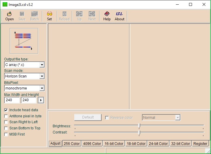
Everything you’re interested in is basically on the left side.
Output file type decides what the output file of the processed image will be. For an MCU, we’re interested in C array (*.c), which we add to our project with source files, and Binary(*.bin), which we can put e.g. on a memory card.
Scan mode sets the order and arrangement of subsequent bytes. This is what I wrote about above when arranging bytes. There’s helpful guidance here in the form of a drawing of these bytes, with MSB (red) and LSC (blue) marked. What I use most often is Horizontal Scan, but not always. For example, the default arrangement of bytes in the RAM memory of an OLED with an SSD1306 controller is Data hor,Byte ver. That’s also how I have the RAM buffer arranged for these OLEDs.
BitsPixel determines the number of colors per pixel. Monochrome is what we care about for a regular OLED. 4 colors is 2 bits, 16 colors 4 bits, 256 colors—8 bits, 4096 colors—12 bits, and then the more clearly labeled 16, 24, and 32 bits per pixel. What’s important here is that pixels will be packed by default, so it’s exactly what we want e.g. for monochrome.
Max Width and Height lets us reduce the image we convert. Instead of resizing the source image, you can just limit it here.
Next there are a few checkboxes. The first one is used to include a header with, among other things, the image size into the whole array. The first 6 bytes then are exactly this header.
The next 3 checkboxes change the byte scan order and swap MSB and LSB within individual bytes.
The last checkbox MSB First is useful when a pixel has more than 1 byte, like in color formats. Then we can decide the order of those bytes.
How Image2Lcd works
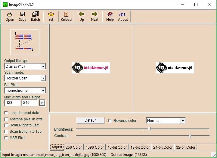
How do we create an image for a microcontroller? We open any file via Open. Let’s take my logo. It can be color.

On the left side I set the output as a C file, mono image, because I have a mono OLED at hand, and I limited the width to 128 pixels. Automatically, the source preview (left) and the resulting image preview (right) were reduced to that size.
At the bottom you have sliders. Depending on what final color format you want, you use the appropriate tab. I increased contrast and brightness so the characteristic elements of my logo stand out.
But heeey! What is that watermark?! Exactly. You must remember to enter the registration key. This program used to be paid, but after it got old, the key was made available and it’s free 🙂
You register in the bottom right in the Register tab. The key is in the package with the program.
Now it’s without the watermark. I noticed that sometimes the registration is not remembered and you have to do it again, so keep the key somewhere in your notes.
Now, when you save the file using the Save button, you’ll get the converted *.C file. It looks like this.
const unsigned char gImage_image[608] = { /* 0X00,0X01,0X80,0X00,0X26,0X00, */
0X00,0X00,0X00,0X00,0X00,0X00,0X00,0X00,0X00,0X00,0X00,0X00,0X00,0X00,0X00,0X00,
0X00,0X05,0X00,0X00,0X00,0X00,0X00,0X00,0X00,0X00,0X00,0X00,0X00,0X00,0X00,0X00,
0X00,0X00,0XFE,0X40,0X00,0X00,0X00,0X00,0X00,0X00,0X00,0X00,0X00,0X00,0X00,0X00,
0X00,0X00,0X6F,0X80,0X00,0X00,0X00,0X00,0X00,0X00,0X00,0X00,0X00,0X00,0X00,0X00,
0X00,0X29,0XC7,0X80,0X00,0X00,0X00,0X00,0X00,0X00,0X00,0X00,0X00,0X00,0X00,0X00,
0X00,0X07,0X9B,0XC8,0X00,0X00,0X00,0X00,0X00,0X00,0X00,0X00,0X00,0X00,0X00,0X00,
0X00,0X03,0X3D,0XF0,0X00,0X00,0X00,0X00,0X00,0X00,0X00,0X00,0X00,0X00,0X00,0X00,
0X01,0X4E,0X7E,0XF0,0X00,0X00,0X00,0X00,0X00,0X00,0X00,0X00,0X00,0X00,0X00,0X00,
0X00,0X3C,0XFF,0X79,0X00,0X00,0X00,0X00,0X00,0X00,0X00,0X00,0X00,0X00,0X00,0X00,
0X00,0X19,0XFF,0XBE,0X00,0X00,0X00,0X00,0X00,0X00,0X00,0X00,0X00,0X00,0X00,0X00,
0X08,0X73,0XFF,0XDE,0X40,0X00,0X00,0X00,0X00,0X00,0X00,0X00,0X00,0X00,0X00,0X00,
0X00,0XE7,0XFF,0XEF,0X80,0X00,0X00,0X00,0X00,0X00,0X00,0X00,0X00,0X00,0X00,0X00,
0X00,0XCF,0XFF,0XF7,0X80,0X00,0X00,0X00,0X00,0X00,0X00,0X00,0X00,0X00,0X00,0X00,
0X43,0X98,0XFE,0X3B,0XC8,0X00,0X00,0X00,0X0C,0X00,0X00,0X00,0X00,0X00,0X01,0X80,
0X4F,0X30,0XC4,0X1D,0XF0,0X00,0X00,0X00,0X0C,0X00,0X00,0X00,0X00,0X00,0X01,0X80,
0X26,0X70,0X00,0X1E,0XF0,0X00,0X60,0X00,0X0C,0X00,0X01,0X80,0X00,0X00,0XD1,0X80,
0X1C,0XF0,0X02,0X1F,0X78,0X76,0XF3,0XC7,0XCC,0X7D,0XDB,0XC7,0X9F,0X81,0XF9,0X80,
0X39,0XF0,0X42,0X1F,0XB8,0X7F,0X76,0X6C,0XCC,0XCD,0XFD,0XCD,0X9F,0X81,0XD9,0X80,
0X33,0XF0,0XC2,0X1F,0XD8,0X77,0X77,0X00,0XCC,0X0D,0XDD,0XDD,0XDD,0XC1,0X99,0X80,
0X33,0XF0,0XC2,0X1F,0XD8,0X77,0X73,0XC7,0XCC,0X7D,0XDD,0XD9,0X99,0X81,0X99,0X80,
0X39,0XF0,0XC2,0X1F,0XB8,0X77,0X61,0XCC,0XCC,0XCC,0XDD,0XDD,0X99,0X81,0X99,0X80,
0X1C,0XF0,0XC6,0X1F,0X78,0X36,0X64,0XEC,0XCC,0XCC,0XD9,0X9D,0X99,0X9D,0XB1,0X80,
0X3E,0X78,0X86,0X1E,0XE0,0X36,0X67,0XC7,0XCC,0X78,0XD9,0X8F,0X19,0X9D,0XE1,0X80,
0X0F,0X38,0X86,0X1D,0XF0,0X00,0X01,0X00,0X0C,0X00,0X00,0X00,0X00,0X01,0X81,0X80,
0X07,0X9F,0XFC,0X3B,0XC8,0X00,0X00,0X00,0X00,0X00,0X00,0X00,0X00,0X01,0X80,0X00,
0X03,0XCF,0XFF,0XF7,0X40,0X00,0X00,0X00,0X00,0X00,0X00,0X00,0X00,0X01,0X80,0X00,
0X01,0XE7,0XFF,0XEF,0XA0,0X00,0X00,0X00,0X00,0X00,0X00,0X00,0X00,0X00,0X00,0X00,
0X0A,0XF3,0XFF,0XDE,0X40,0X00,0X00,0X00,0X00,0X00,0X00,0X00,0X00,0X00,0X00,0X00,
0X00,0X79,0XFF,0XBA,0X00,0X00,0X00,0X00,0X00,0X00,0X00,0X00,0X00,0X00,0X00,0X00,
0X00,0X3C,0XFF,0X79,0X00,0X00,0X00,0X00,0X00,0X00,0X00,0X00,0X00,0X00,0X00,0X00,
0X01,0X4E,0X7E,0XF0,0X00,0X00,0X00,0X00,0X00,0X00,0X00,0X00,0X00,0X00,0X00,0X00,
0X00,0X0F,0X3D,0XD0,0X00,0X00,0X00,0X00,0X00,0X00,0X00,0X00,0X00,0X00,0X00,0X00,
0X00,0X07,0X9B,0XC8,0X00,0X00,0X00,0X00,0X00,0X00,0X00,0X00,0X00,0X00,0X00,0X00,
0X00,0X29,0XC7,0X80,0X00,0X00,0X00,0X00,0X00,0X00,0X00,0X00,0X00,0X00,0X00,0X00,
0X00,0X01,0XEE,0X80,0X00,0X00,0X00,0X00,0X00,0X00,0X00,0X00,0X00,0X00,0X00,0X00,
0X00,0X00,0XFE,0X40,0X00,0X00,0X00,0X00,0X00,0X00,0X00,0X00,0X00,0X00,0X00,0X00,
0X00,0X05,0X00,0X00,0X00,0X00,0X00,0X00,0X00,0X00,0X00,0X00,0X00,0X00,0X00,0X00,
0X00,0X02,0X00,0X00,0X00,0X00,0X00,0X00,0X00,0X00,0X00,0X00,0X00,0X00,0X00,0X00,
};
The first thing I do is change the variable type to uint8_t and remove the gImage_ prefix from the array. That’s how I like it.
const uuint8_t image[608] = { /* 0X00,0X01,0X80,0X00,0X26,0X00, */
The file is 608 bytes. What size is the image? We can either check it in the program.

You can also do it better. You can tick Include head data and have it in our image array. Thanks to this we can write code in such a way that it checks the dimensions by itself. If you don’t tick it, then the header is still in the array, but commented out.
const uint8_t image[608] = { /* 0X00,0X01,0X80,0X00,0X26,0X00, */
These 6 bytes are /* 0X00,0X01,0X80,0X00,0X26,0X00, */ – is MSB first – NO. This affects the byte order in the image dimensions!
/* 0X00,0X01,0X80,0X00,0X26,0X00, */ – bits per pixel = 1
/* 0X00,0X01,0X80,0X00,0X26,0X00, */ – pixels horizontally – 0x0080 = 128
/* 0X00,0X01,0X80,0X00,0X26,0X00, */ – pixels vertically – 0x0026 = 38
You can already use such an array in your project. It works similarly with color images.
Summary
As you can see, creating an image for a microcontroller is a piece of cake! Why search and reinvent the wheel when you could have asked me how to do it 🙂
Now you just need to generate it, put it into Flash, and display your graphics. The only thing missing is some kind of compression like RLE. I use it incredibly rarely myself, so I don’t have a solution for this problem at the moment. If there’s a need, I’ll look for something.
If you liked the article, buy something from me! 🙂 https://sklep.msalamon.pl/
If you noticed an error, disagree with something, would like to add something important, or simply feel like you’d like to discuss this topic, write a comment. Remember that the discussion should be polite and compliant with the rules of the Polish language.
Table of contents for the entire SSD1327 OLED series:
Grayscale OLED on SSD1327 part 1
Grayscale OLED on SSD1327 part 2
How to prepare an image for an LCD or TFT display?
Grayscale OLED on SSD1327 part 3
Podobne artykuły





0 Comments