Distance measurement is used in everyday life, for example in parking sensors in cars. For robots, distance sensors help them survive a thicket of obstacles, e.g., so that a drone doesn’t smash its propellers against a pole or a wall. Let’s take a look at a very cheap HC-SR04 ultrasonic rangefinder – how it works and how to use it optimally.
Ultrasonic rangefinder HC-SR04
The HC-SR04 ultrasonic sensor is powered by 5 V with a current draw of about 15 mA in the active state. The distance it can measure is in the range of 2÷400 cm. The measurement cone is 15°, hence the best results at maximum distance are obtained with an object larger than 0.5 m². The closer the object is, the smaller it can of course be.
The distance measurement module uses 40 kHz ultrasound, which is far beyond the human hearing range. The sensor is built from two ultrasonic elements – a transmitter and a receiver. The operation scheme of each measurement is as follows:
- To start a measurement, a high state lasting at least 10 µs must be applied to the TRIG pin.
- The module starts a timer and sends 8 ultrasonic pulses.
- It waits until the reflected beam returns to the receiver, which is right next to the transmitter.
- When it detects the reflected signal, it stops the counter.
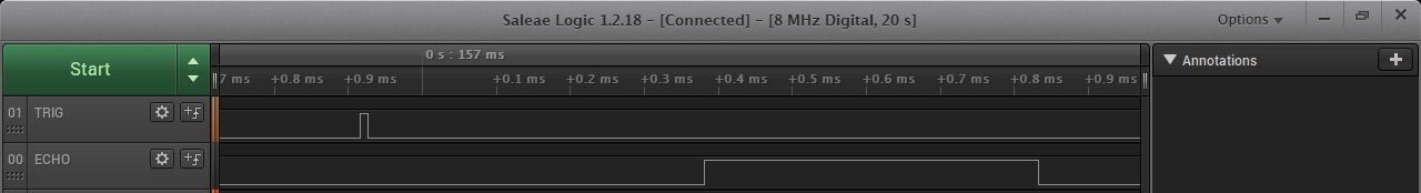
- The total time of flight of the ultrasonic pulse is reflected by the pulse length on the ECHO pin.
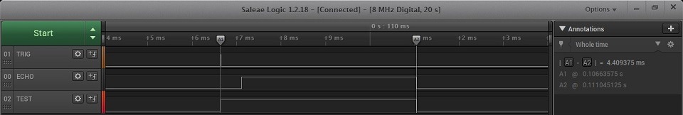
This is what it looks like on the analyzer.
How to calculate the distance? The formula is quite simple: Distance = Wave propagation speed * time. We have time measured with a counter. Remember that this is the time the ultrasonic wave needs to travel to the object and back. The propagation speed in air is 343 m/s, i.e., 34300 cm/s if you want the result in centimeters. The time reported by the sensor is in µs. To obtain seconds, simply divide by 1,000,000. Ultimately Distance[cm]= Time[µs] / 2 * 0.0343[cm/µs]. You can also compute it more simply by starting from how long it takes the wave to travel one centimeter, which is about 29 µs/cm. The formula will then be: Distance[cm]= Time[µs] / 58[µs/cm]. In this case we won’t know decimal parts of a centimeter, but we avoid float in the calculations because How much does using float cost and what does FPU give?. In the library I provided the option to choose the calculation method via the definition #define HCSR04_HIGH_PRECISION which, when uncommented, selects float calculations.
Schematic and Cube
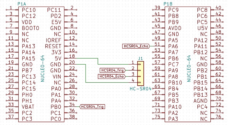
For the tests I chose the Nucleo STM32L476RG from one of my kits. Since the sensor operates at 5 V, you must be careful how you connect it! Especially the Echo pin, which is the output from the module and will be at 5 V in the high state. STM32 works in the 3.3 V domain, but fortunately some of its pins are 5 V tolerant, which I wrote about in the post Why STM32?. You should check in the documentation which ones you can safely connect to. I chose pins PA6 (5 V tolerant) for ECHO and PB0 (3.6 V tolerant) for TRIG. A 3.3 V level driven from a GPIO will be sufficient to drive the Trigger.

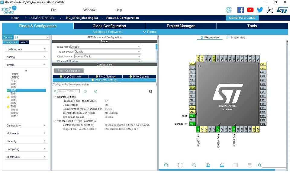
First, let’s check a simple blocking approach. For this we need some timer that we can use at microsecond resolution. The maximum response from the HC-SR04 can be about 4 ms, so a 16-bit TIM3 counter will be more than enough, and that’s what I’ll take. I set the main HCLK frequency to 48 MHz. To obtain a microsecond tick of the timer it is enough to divide this frequency by 48. For this, I set the prescaler to 47. I also change the maximum value to which the counter can count. I set it to the largest possible – 65535. Counting is left at the default – up. I do not enable any interrupts.
Blocking measurement
In the “budget edition”, as in most examples for popular Arduino, the microcontroller will wait for the ECHO signal from the sensor to finish to provide the pulse length.
The initialization function takes a pointer to a timer configured earlier for a microsecond tick .
HCSR04_STATUS HCSR04_Init(TIM_HandleTypeDef *htim);
This function is responsible for starting the counter and setting the TRIG pin low.
The second useful function is the distance measurement, which returns the measured distance in centimeters through a pointer to a float.
HCSR04_STATUS HCSR04_Read(float *Result);
This function sets the TRIG pin high for 10 µs and then waits for a high state to appear on the ECHO pin. When it appears, it zeros the timer and in a loop waits for a low state on ECHO. After the echo signal ends, the conversion is performed and the result is written to the indicated variable. As you can see, the operation is simple. Unfortunately, the microcontroller actually waits idly for changes in the ECHO pin state. This may not be much time, but it depends on the measured distance. For small distances the total handling time will be about a millisecond, but for larger ones it will be much longer, as can be seen in the waveforms below.
How to do it better?
Non-blocking handling of the HC-SR04
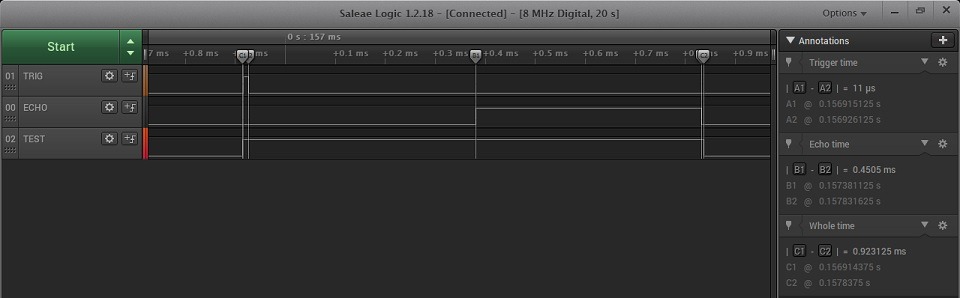
For non-blocking handling of the sensor I will use the modes that timers in STM32 offer. To trigger the measurement I will use PWM at a frequency of about 15 Hz (period = 65535 microseconds) with a high-state duration of 11 µs (0.022%). Some sources state that 20 Hz is the maximum refresh rate for this sensor. I couldn’t find this in official documents, so I accept that value as correct. However, for convenience of using a single counter (1 µs tick) for the complete handling of the measurement, I will use the aforementioned 15 Hz.
To capture the ECHO signal I will use the Input Capture mode, which will capture both edges on the ECHO pin. The signal from this pin will be physically routed to TIM3 CH1. This channel will latch the counter value when it detects a rising edge on pin PA6, i.e., it will capture the counter value at the start of the measurement pulse. The falling edge, i.e., the end of the measurement, will be detected by TIM CH2 and will latch the counter value in the appropriate register. In the STM32 configuration it will be internally connected to the physical CH1 pin, i.e., PA6. Thanks to this I can distinguish and handle two different events on a single pin.
I trigger an interrupt only after latching the value on the falling edge. In the interrupt handler I subtract the value of the register responsible for the end of the measurement from the register holding the value from the beginning of the measurement. By using the full 16-bit range of the timer I do not have to worry about a possible counter overflow between the start and the end. 16-bit arithmetic elegantly handles such cases on uint16_t numbers. I put this difference into the equation from the beginning of the post and I already have the calculated distance to the obstacle from the sensor.
The CPU time now needed to handle the sensor is almost negligible. See for yourself.

The measurement, as I said, is performed at about 15 Hz.

To maintain compatibility with the blocking library, the read simply returns the library variable into which the interrupt places the result of its operation.
I added the definitions of the timer channels configured for the sensor to the header file. If you use others – change them.
Also remember to add interrupt handling to the HAL _weak function.
/* USER CODE BEGIN 4 */
void HAL_TIM_IC_CaptureCallback(TIM_HandleTypeDef *htim)
{
  HCSR04_TIM_IC_CaptureCallback(htim);
}
/* USER CODE END 4 */
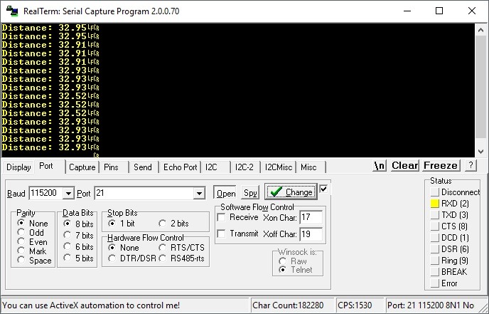
With the sensor facing a wall there are some fluctuations. You could eliminate them with some filtering. A simple moving average of the last few measurements would be enough which, as you remember, we have at about 15 per second.
Summary
As you can see, it’s worth using the hardware capabilities that STM32s offer. Thanks to this, the microcontroller can deal with something more sensible than idly waiting for the measurement to finish. You could also try implementing a filter, e.g., Kalman, to eliminate measurement fluctuations with such frequent measurements, although from my observations on the terminal it wasn’t that bad.
If you liked the sensor, you can buy it in my store.
Projects with the blocking and non-blocking versions can be found on my GitHub: blocking, non-blocking
If you noticed any error, disagree with something, would like to add something important or simply want to discuss this topic, write a comment. Remember that the discussion should be polite and in accordance with the rules of the Polish language.
Podobne artykuły


0 Comments