The real-time clock in STM32 microcontrollers is not the same across all families. Basically, we can encounter two different RTCs. One basic one, which is found in older and less advanced microcontrollers like the F1 series, which I covered in previous articles. There is also a more advanced clock, which you can find for example in the F4 family, and that’s exactly what I’m going to take a look at this time.
RTC in STM32F4
As I mentioned, in ST32F4 the RTC block is more advanced. In F1 we had only one 32-bit counter, which was able to count single seconds without distinguishing other components of the date or time. It was up to the programmer how to use those seconds to compose the date and time.
In F4, however, the clock has been equipped with additional counters, which are split into smaller chunks that already represent a specific hour, minute, or second.
Additionally, a separate counter was added whose job is to take care of counting the date. You could say that the hardest part of the library has been taken off our shoulders, right? Recently with the F1 I had to struggle a bit to make the date work correctly with backup power… We’ll see how it will be here 🙂
However, these are not all the additions present in the RTC for F4. Take a look at the comparison of the number of registers from the Reference Manuals of STM32F103C8T6 and STM32F401CCU6.
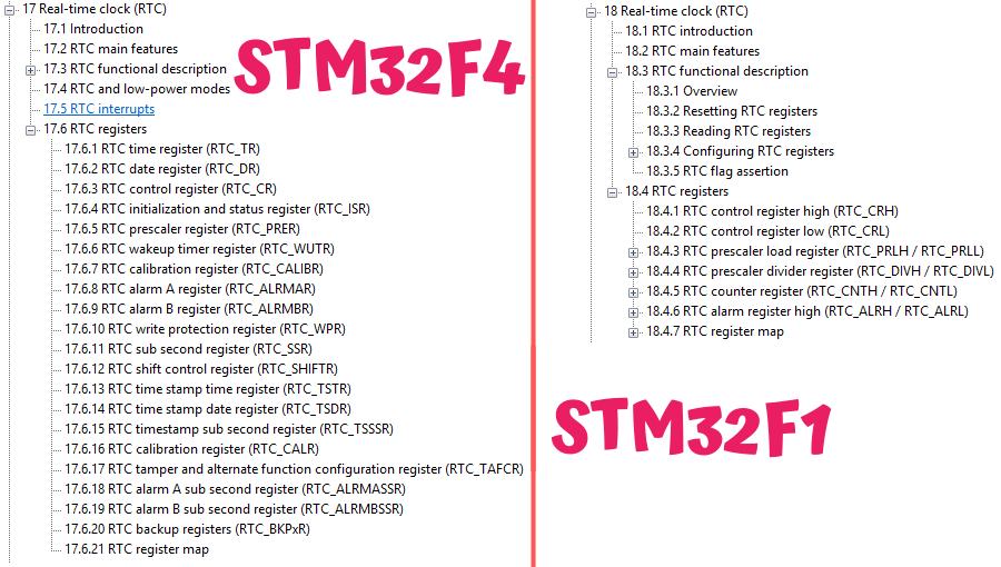
The list is much longer! One could say that the RTC has also become more complicated to handle, because for example the procedures for writing to registers are a bit more demanding in F4 compared to F1. Fortunately, HAL allows us not to worry too much about these procedures.
Additional RTC features
Among the additions that came to the RTC, you can notice, for example, a second alarm. Now there are two – A and B. By the way, write in the comments how you can use an alarm in an interesting way. Preferably something non-obvious 🙂
A cool feature you’ll find in the advanced RTC are registers related to “subseconds”. What is this mysterious “subsecond”? We know, for example, milliseconds, which we can use in electronics, but some kind of sub??
These subseconds are also fractions of a second, but the second is divided a bit differently. We have the ability to set into how many parts the second should be divided. There is also the possibility to set the RTC prescaler, but be careful, because fiddling with these registers can easily make your second drift. The default settings work well. Later I’ll show you how to extract milliseconds from these numbers.
It’s worth paying attention to the registers related to the Wake Up function. It allows waking the microcontroller from reduced power consumption modes. A very useful thing, especially in L-series microcontrollers, which we use for low-power applications.
There is also something called Time Stamp. You can latch the date and time based on an edge on a dedicated pin. Latching works in various low-power modes. You can combine it with the Tamper function, i.e., clearing backup registers after a “break-in”.
Of course, there are also backup registers, and we additionally have a few extra calibration registers at our disposal.
Test platform

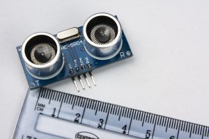
Previously I used BluePill, so now I’ll take something similar. This is, in a way, its successor called BlackPill. I recently described these boards. I took the version with STM32F401CC.
The software I will use is:
- STM32CubeIDE v1.2.0
- STM32CubeMX v5.5.0 built into the IDE
- HAL F4 v1.24.2
Configuration in CubeMX
For test purposes, besides the RTC I need a few other things.
First, the clocks:
- I set HCLK to the maximum value of 84 MHz using the internal HSI oscillator.
- As the clock source for the RTC, I initially chose LSI. Of course, I’ll also check operation with LSE.
For debugging purposes I used:
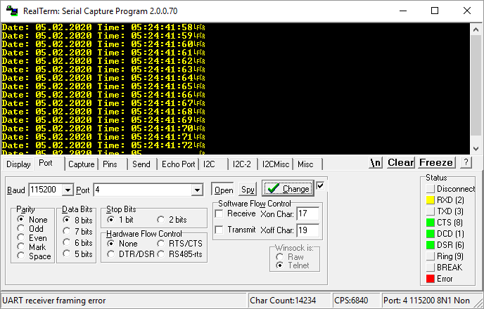
- UART2 in the 115200 8n1 configuration
- Serial Wire in the System Core > SYS > Debug > Serial Wire tab
- GPIO input PA10 labeled as TEST for manually setting the date and time.
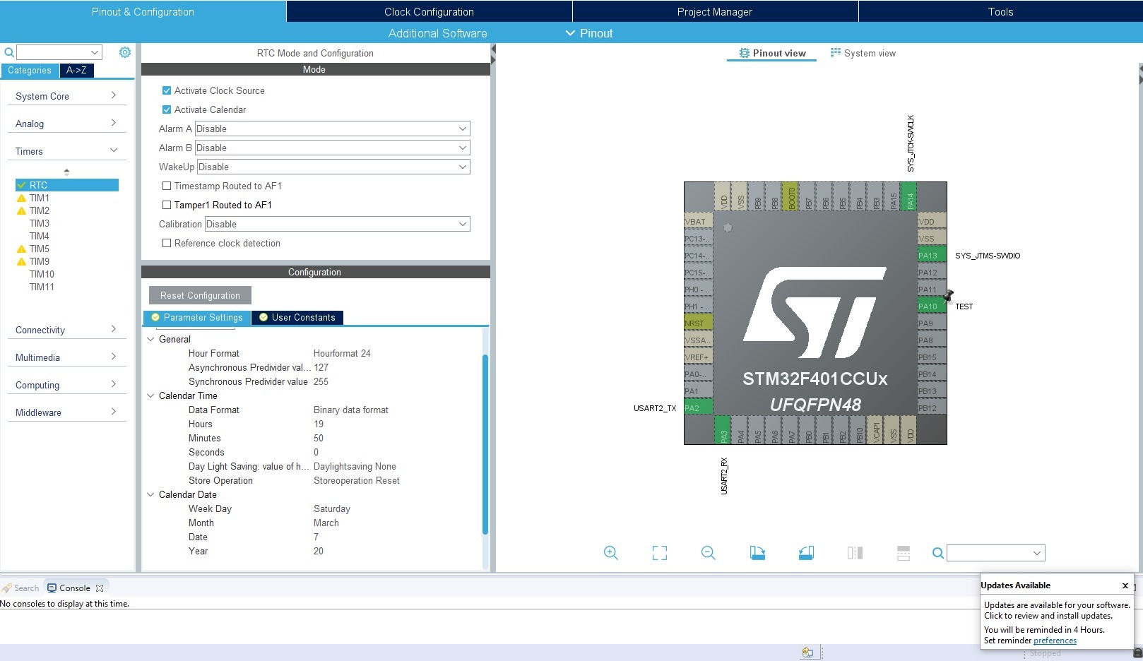
Now you can calmly set the RTC in the Timers tab.
The configuration is similar to the one from F1. Check Activate Clock Source to provide the clocking and enable the RTC.
Additionally, activate the calendar. This time it won’t be adding a software calendar from the library like before, but using the hardware one provided by the RTC.
Set the date and time you want. In STM32F4 you also have information whether it’s daylight saving time or standard time. You store the year in the range 0–99.
This way configured project can be generated.
RTC code
In the project we got a generated library to use the RTC. Just like before, it contains structures responsible for holding time and date.
/**
  * @brief  RTC Time structure definition
  */
typedef struct
{
  uint8_t Hours;            /*!< Specifies the RTC Time Hour.
                                 This parameter must be a number between Min_Data = 0 and Max_Data = 12 if the RTC_HourFormat_12 is selected.
                                 This parameter must be a number between Min_Data = 0 and Max_Data = 23 if the RTC_HourFormat_24 is selected  */

  uint8_t Minutes;          /*!< Specifies the RTC Time Minutes.
                                 This parameter must be a number between Min_Data = 0 and Max_Data = 59 */

  uint8_t Seconds;          /*!< Specifies the RTC Time Seconds.
                                 This parameter must be a number between Min_Data = 0 and Max_Data = 59 */

  uint8_t TimeFormat;       /*!< Specifies the RTC AM/PM Time.
                                 This parameter can be a value of @ref RTC_AM_PM_Definitions */

  uint32_t SubSeconds;     /*!< Specifies the RTC_SSR RTC Sub Second register content.
                                 This parameter corresponds to a time unit range between [0-1] Second
                                 with [1 Sec / SecondFraction +1] granularity */

  uint32_t SecondFraction;  /*!< Specifies the range or granularity of Sub Second register content
                                 corresponding to Synchronous pre-scaler factor value (PREDIV_S)
                                 This parameter corresponds to a time unit range between [0-1] Second
                                 with [1 Sec / SecondFraction +1] granularity.
                                 This field will be used only by HAL_RTC_GetTime function */

  uint32_t DayLightSaving;  /*!< Specifies DayLight Save Operation.
                                 This parameter can be a value of @ref RTC_DayLightSaving_Definitions */

  uint32_t StoreOperation;  /*!< Specifies RTC_StoreOperation value to be written in the BCK bit
                                 in CR register to store the operation.
                                 This parameter can be a value of @ref RTC_StoreOperation_Definitions */
}RTC_TimeTypeDef;

/**
  * @brief  RTC Date structure definition
  */
typedef struct
{
  uint8_t WeekDay;  /*!< Specifies the RTC Date WeekDay.
                         This parameter can be a value of @ref RTC_WeekDay_Definitions */

  uint8_t Month;    /*!< Specifies the RTC Date Month (in BCD format).
                         This parameter can be a value of @ref RTC_Month_Date_Definitions */

  uint8_t Date;     /*!< Specifies the RTC Date.
                         This parameter must be a number between Min_Data = 1 and Max_Data = 31 */

  uint8_t Year;     /*!< Specifies the RTC Date Year.
                         This parameter must be a number between Min_Data = 0 and Max_Data = 99 */

}RTC_DateTypeDef;
Variables corresponding to additional features were added, such as the time format (12/24H) or daylight saving/standard time. There is also information about subseconds, and based on it we will calculate milliseconds.
Reading data from the RTC looks literally the same as in the case of F1.
HAL_RTC_GetTime(&hrtc, &RtcTime, RTC_FORMAT_BIN);
HAL_RTC_GetDate(&hrtc, &RtcDate, RTC_FORMAT_BIN);
BUT there is one condition here. You MUST always read the time first, and then the date. It’s even written in the comment for these functions.
  * @note You must call HAL_RTC_GetDate() after HAL_RTC_GetTime() to unlock the values
  *        in the higher-order calendar shadow registers to ensure consistency between the time and date values.
  *        Reading RTC current time locks the values in calendar shadow registers until current date is read.
This is related to so-called shadow registers. At the moment you start reading the time, the data is latched to preserve data consistency and correct reading. While you are reading, the RTC continues counting in those hidden registers, whereas the ones available to the user are latched.
You have to read everything for the registers to unlock again. I know this causes a lot of problems for beginners 🙂
Overwriting the date at startup
Unfortunately, this problem also exists in the library, and we solve it similarly to the STM32F1 library via return in the backup registers restore section.
  /* USER CODE BEGIN Check_RTC_BKUP */
  HAL_RTC_GetTime(&hrtc, &RtcTime, RTC_FORMAT_BIN);
  HAL_RTC_GetDate(&hrtc, &RtcDate, RTC_FORMAT_BIN);
  return;
  /* USER CODE END Check_RTC_BKUP */
On startup, we can also read what is currently in the RTC.
And that’s it! Really. Looking at my previous struggles with the ST library, it’s hard to believe. However, for F4 the library is better written. I dare say it was written first for F4, and only later more or less mindlessly ported to F1.
BlackPill battery supply
Do you remember the weird behavior of BluePill, which was that when you connected a battery to VBAT, the RTC still didn’t run without MCU power?
The problem was the lack of a capacitor at the VBAT pin. Adding 100 nF fixed it. How is it in BlackPill? Here, according to the schematic, such a capacitor is placed. However, it’s not known what value it has. I’ll check whether it works anyway.
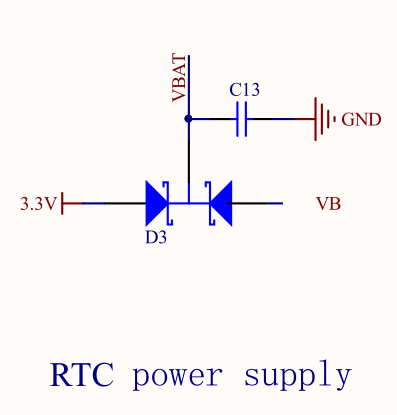
And… it works. The RTC runs on the battery alone. A big advantage of BlackPill over BluePill, if you’re starting with programming and you practically have no chance of catching such an error yourself.
External LSE resonator
With BluePill there was one more problem. This time related to the external resonator for the RTC. The error was that the oscillator pins were also routed to header pins, which caused frequency fluctuations and incorrect time counting. How is it in BlackPill? I’ll also take a look at the schematic.
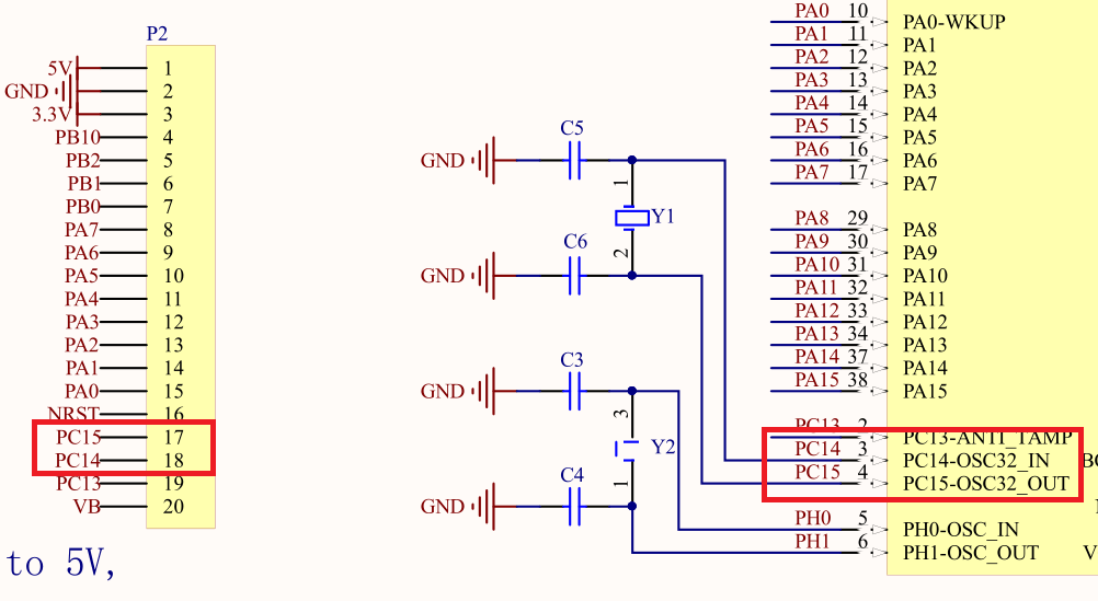
Unfortunately, the same mistake was made here. If you want to use the oscillator placed on the board, you must remove the header pins for PC14 and PC15, otherwise the RTC will count time incorrectly.
Milliseconds
At the beginning I mentioned that we are able to pull milliseconds from the built-in RTC in F4. They can be useful, for example, for printing logs from the microcontroller’s operation.
To calculate milliseconds I will use the SubSeconds and SecondFraction variables, which are in the structure that stores time. These data are read from the RTC registers.
In the description of the time reading function we have such a note.
  * @note  You can use SubSeconds and SecondFraction (sTime structure fields returned) to convert SubSeconds
  *        value in second fraction ratio with time unit following generic formula:
  *        Second fraction ratio * time_unit= [(SecondFraction-SubSeconds)/(SecondFraction+1)] * time_unit
  *        This conversion can be performed only if no shift operation is pending (ie. SHFP=0) when PREDIV_S >= SS
It provides a formula that you need to use. The result you get is expressed in hundredths of a second, e.g. 0.67 s, i.e. 67 hundredths. I wouldn’t like to store the number of milliseconds as a floating-point value, so I’ll multiply the result by 1000. However, it still won’t work, because you still have to perform division by float along the way.
Ultimately, the code calculating the number of milliseconds looks like this.
Milliseconds = ((RtcTime.SecondFraction-RtcTime.SubSeconds)/((float)RtcTime.SecondFraction+1) * 100);
Now you can print the milliseconds. It works quite nicely 🙂

Summary
My experience working with the RTC in STM32F4 is much better than with F1. Mainly thanks to the better-working library from ST, which can be successfully used right away. And what’s your opinion?
In the next article we will check those additional RTC functions. I’ll show you how to set them up and how things like Alarm, WakeUp, or Time Stamp work.
You can find the full project along with the library, as usual, on my GitHub: LINK
If you noticed an error, disagree with something, would like to add something important, or simply feel like you’d like to discuss this topic, write a comment. Remember that the discussion should be polite and in accordance with the rules of the Polish language.
Podobne artykuły


0 Comments