I remember when I wanted to use EEPROM in STM32 for the first time. Everything went great until the moment I actually wanted to use that memory. It turned out that… not all STM32s have EEPROM! Those lacking this feature are especially the F series. What to do in such a situation? You can use an external I2C/SPI chip or… emulate EEPROM in the built-in FLASH memory. Come, I’ll show you how to do it.
How does EEPROM work?
I think the first thing is to know what EEPROM is. It is non-volatile memory, meaning its contents are not lost when power is removed. Of course, you can read from it and it has no effect on the data stored in the memory or their lifetime. It is also possible to write, starting from a single byte. An advantage of EEPROM is also that you can quickly write both “zeros” and “ones,” which is not so obvious in the case of FLASH memory. Access to each byte, both for reading and writing, is random.
In this post I deal with EEPROM emulation in the microcontroller’s internal FLASH memory. How does FLASH memory work? The behavior is very similar to EEPROM with one “small” difference. Erasing memory (which is most often writing 0xFF into a cell) is not so free. It is performed in larger areas called sectors or pages depending on the documentation. This is the so-called FLASH erase. These sectors can have different sizes, e.g. 1 kB or even 128 kB. Writing to FLASH is actually setting “zeros” among a fence of “ones.”
Because FLASH memory requires specific erasing, it is not possible to emulate EEPROM behavior 1:1. You cannot allocate a few bytes of FLASH for a few variables because we are not able to “write” ones. Example: attempting to overwrite 0xF0 with the value 0xFF in FLASH memory will not succeed.
The principle is the same for both families. I will briefly discuss how the emulation works.
Data representation
Data in FLASH is stored in 32-bit cells. These cells are divided into two parts. One is a 16-bit virtual address of the EEPROM variable. The other part is the value of that variable. Why so? Because each variable update writes its new value to the next free FLASH cell. We do not overwrite the old value.
Why do we need two memory pages?
If each new value of a variable is written to a new cell, eventually those cells will run out. When that happens, the old page is designated for data transfer to a new page. We do not transfer all data. We are not interested in historical data of variables, so we scan the full page from the end and transfer the newest values of variables to the new page. After moving to the new page, it is marked as active, and the old one will be erased entirely (erasing the whole FLASH page).
Reading from the emulated EEPROM
To read a variable at the appropriate virtual address, you need to scan the entire page written so far. Each time a variable with the virtual address we require is encountered, its value is remembered. The next encounter of the same variable updates the remembered temporary value. The search continues until we encounter an erased cell, i.e., one with a virtual address of 0xFFFF. Hence the use of this virtual address is forbidden. The last remembered value is returned as the one currently stored in our EEPROM.
Writing to the emulated EEPROM
Writing searches for the first free cell on the memory page. If it finds one, it writes the given virtual address and the value we provide. If there are no free cells on the page, the procedure of transferring the newest copies of variables with unique virtual addresses begins. Only after that will our variable be written to the first free cell on the new page. The old one will be erased. The pages are used alternately in this way.
Data update flow
You will find the entire process of writing sample data and transferring it to a new page illustrated in the documentation for F1 (p. 8) and F4 (p. 11).
EEPROM emulation library
Reading the documentation and devising a library for correct EEPROM emulation behavior can make your head spin a bit. Fortunately, ST has prepared an appropriate library. In addition, it works out of the box with our favorite HAL. The entire library boils down to only three functions, which makes it incredibly simple to use. You can, however, stretch your brain a bit with its configuration in the eeprom.h file. That’s where the complete configuration of the EEPROM emulator is located. Let me first discuss this configuration. The definitions we are interested in are:
#define PAGE_SIZE – defines the size of the pages to be used. You can find this information in the microcontroller’s Reference Manual or in the HAL libraries.
#define EEPROM_START_ADDRESS – from which address in memory the EEPROM emulation will be located. I recommend using the end of FLASH so as not to collide with the main program. This address will be the address of the first FLASH page used.
#define PAGE0_BASE_ADDRESS #define PAGE0_END_ADDRESS #define PAGE0_ID – the start and end addresses of the zeroth emulation page and the ID of the first page in FLASH. The same exists for PAGE1 of the EEPROM.
#define PAGE0 #define PAGE1 – the description in the header is misleading and talks about how many FLASH pages are used for EEPROM pages. In fact, the important definition is PAGE1, which says how many pages away it is relative to the start of PAGE0. If you want to use 2 FLASH pages per one EEPROM page, you will enter the number 0x2 in PAGE1.
#define NB_OF_VAR – the number of unique variables we want to store in the emulated EEPROM. This is important because the library needs a table of virtual addresses and you have to create it earlier in the program.
Library functions
As I mentioned, the user has 3 simple functions at their disposal. Here they are:
uint16_t EE_Init(void) – initializes the EEPROM emulator. It checks whether pages were previously written (by the header) and whether they need to be erased. Restores usability after power loss.
uint16_t EE_ReadVariable(uint16_t VirtAddress, uint16_t* Data) – Reads a variable from EEPROM. The variable at the virtual address VirtAddress will be placed in the memory pointed to by Data.
uint16_t EE_WriteVariable(uint16_t VirtAddress, uint16_t Data) – Writes to EEPROM. The variable at the virtual address VirtAddress will be written with the value Data.
All these functions return status codes compatible with HAL.
Simple to use, right? Time to work with real devices.
EEPROM emulation on STM32F103C8T6
First, I took the popular BluePill. Allow me to skip the Cube configuration and the schematic this time. They’re not important in this exercise. I only configured the built-in LED and UART2 to send the contents of the emulated EEPROM to the terminal.
Configuration
For proper configuration I will need the Reference Manual with the FLASH memory map of the microcontroller.
We are interested in Main memory. We have 128 pages of 1 kB each. For tests I can use the last two. In general, I would recommend using the ending pages.
In the eeprom.h header file you can notice that the addresses of each page are already predefined. You could even skip looking at the documentation to configure it correctly, but it’s better to make sure no one made a mistake in the code.
The page size is already defined in the HAL library. You can just make sure it is about 1 kB, i.e., 0x400.
We want to use the last two pages, so I set EEPROM_START_ADDRESS to the penultimate page, which is ADDR_FLASH_PAGE_126.
Now the addresses of the two EEPROM emulation pages and the number of pages used. You can use the previously predefined addresses or play with offsets.
It is very important to unlock FLASH from the program level before using the function that initializes the library.
HAL_FLASH_Unlock();
Now you can initialize the EEPROM.
if( EE_Init() != HAL_OK)
{
  Error_Handler();
}
From now on, you can use the EEPROM. In the program I created an array with sample data that I will write to EEPROM. It contains the string “Mateusz Salamon msalamon.pl”. It consists of 27 characters, which I previously took into account in the configuration.
In the program I write and read this data from the EEPROM according to the scheme:
Write the data to EEPROM. Each character at its unique virtual address.
Read and print to the terminal
Write the data to EEPROM in reverse order.
Read and print to the terminal. The text should be reversed.
Write the data to EEPROM.
Read and print to the terminal. The effect is the same as in pt. 2
You can see the effects from the terminal in the screenshot.
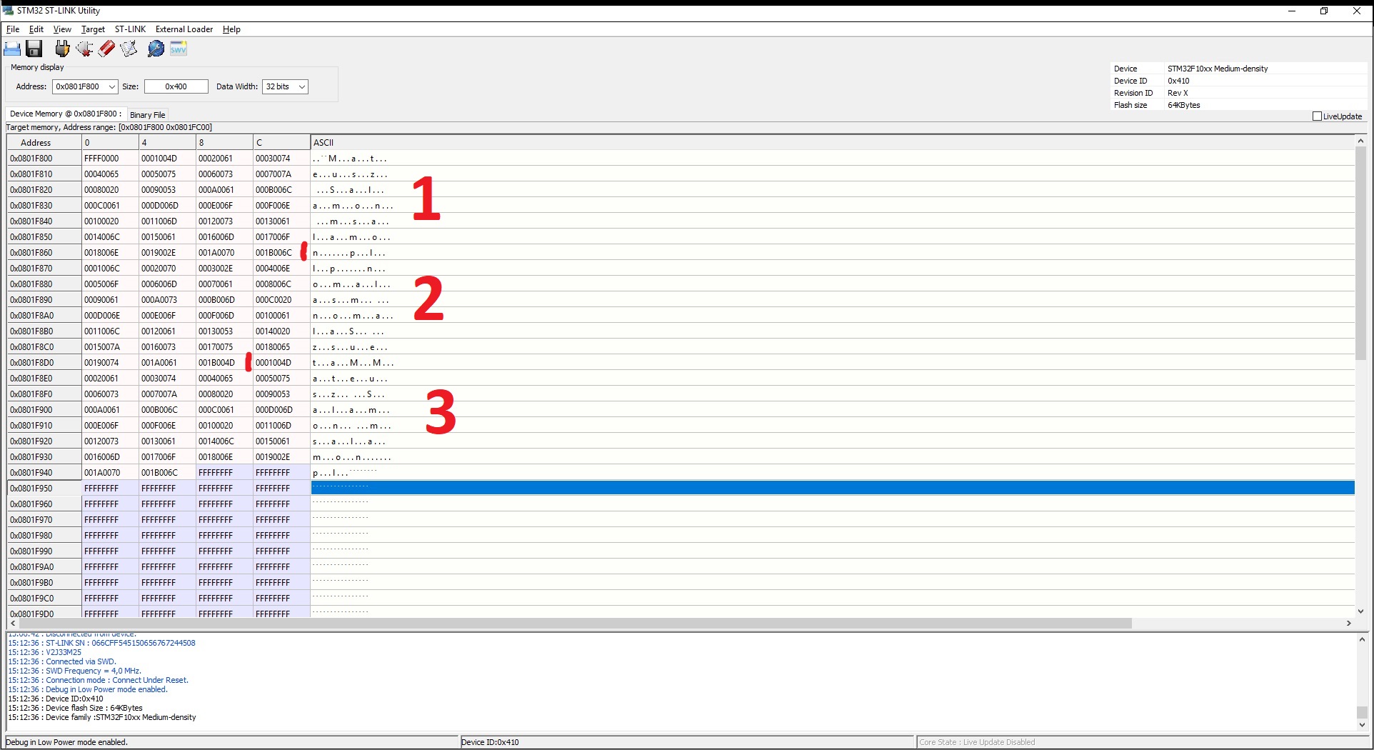
And what happens to FLASH memory? What do I expect? According to the EEPROM emulation documentation, the text should land under variables with virtual addresses 1–27 first in normal order, then reversed, and finally normal again. The result is below.
Data marked 1 are from the first write. 2 is the reversed write. 3 is a subsequent write in normal order. Please analyze this data. The first cell at the top left is the page header. It is in the ERASED state, so you can write to this page.
Then there is the data. The first 16 bits (4 digits) are the virtual address of each variable. The second 16 bits are the value, i.e., the characters from the string.
EEPROM emulation on STM32F401RE
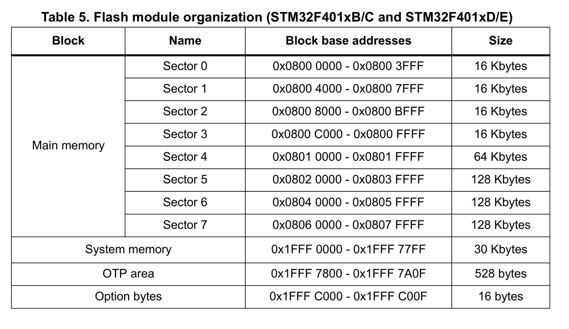
The organization of memory in microcontrollers can vary. For this reason, you should always check the documentation. In the F4 series we can be slightly surprised because the FLASH memory looks like this:
We have only 8 sectors and they are not equal in size. Remember that FLASH erasing is done per entire sector. It would be sad to use 256 kB of FLASH for a few EEPROM variables. That’s why I will use sectors 2 and 3. Configuration:
/* Define the size of the sectors to be used */
#define PAGE_SIZE (uint32_t)0x4000 /* Page size = 16KByte */

/* Device voltage range supposed to be [2.7V to 3.6V], the operation will
be done by word */
#define VOLTAGE_RANGE (uint8_t)VOLTAGE_RANGE_3

/* EEPROM start address in Flash */
#define EEPROM_START_ADDRESS ((uint32_t)0x08008000) /* EEPROM emulation start address:
from sector2 : after 16KByte of used
Flash memory */

/* Pages 0 and 1 base and end addresses */
#define PAGE0_BASE_ADDRESS ((uint32_t)(EEPROM_START_ADDRESS + 0x0000))
#define PAGE0_END_ADDRESS ((uint32_t)(EEPROM_START_ADDRESS + (PAGE_SIZE - 1)))
#define PAGE0_ID FLASH_SECTOR_2

#define PAGE1_BASE_ADDRESS ((uint32_t)(EEPROM_START_ADDRESS + 0x4000))
#define PAGE1_END_ADDRESS ((uint32_t)(EEPROM_START_ADDRESS + (2 * PAGE_SIZE - 1)))
#define PAGE1_ID FLASH_SECTOR_3

/* Used Flash pages for EEPROM emulation */
#define PAGE0 ((uint16_t)0x0000)
#define PAGE1 ((uint16_t)0x0001) /* Page nb between PAGE0_BASE_ADDRESS & PAGE1_BASE_ADDRESS*/
The number of variables I set the same as for F1
/* Variables' number */

#define NB_OF_VAR ((uint8_t)27)
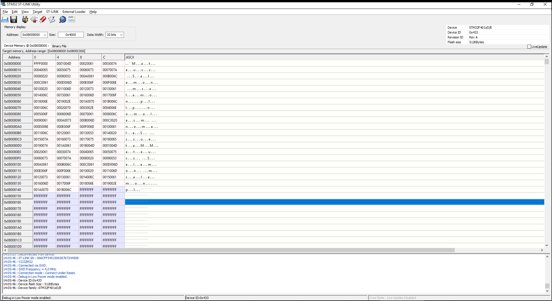
The code in main.c is the same. The result on the terminal is identical to F1, and in FLASH memory it looks similar, except at a different address.
I also checked how long it takes to write and read my character array.
173 ms for write and 3.24 ms for read. Interestingly, these values do not change significantly with increasing FLASH occupancy. There is one moment when this time will be very large. This is the transfer of data to a new EEPROM page and the erasing of FLASH sectors.
EEPROM emulation before the main program
As you probably noticed, I defined EEPROM emulation in the middle of the F401RE FLASH. I would be reluctant to use half of the available memory for EEPROM if I defined it on the last two sectors.
For this reason, I came up with the idea to put the EEPROM on the first two sectors and move the main program to sector 2. Unfortunately, performing this operation causes some error in the program’s operation and the microcontroller crashes… I dug into the code a bit and found a problem in the function that verifies whether the page is erased. It is used in the initialization where the program crashes. There is even a thread on ST’s forum regarding this bug.
Unfortunately, my attempts to fix this snippet did not help. Perhaps the problem is still somewhere else, or it is simply not possible to swap EEPROM with the main program.
The only thing that comes to my mind while writing this article is to split the project into a bootloader and a main program. The bootloader would be run from the starting address and would jump to the main application, which is located after the next two empty sectors. Then the piece of FLASH between the bootloader and the main program could be used for EEPROM emulation 🙂
Summary
Is it worth using EEPROM emulation? Judging by the fact that the code has had easy-to-find bugs for many years, I suspect few people use it. The operation of EEPROM emulation is also not ideal. It takes at least two sectors (pages) of FLASH memory.
As you saw, in F4 series microcontrollers, EEPROM emulation can be very troublesome due to the different sizes of memory sectors.
There is one more issue I did not address. The lifetime of this solution. FLASH memory is not a longevity champion. A single memory cell can withstand only about 10 thousand write cycles. This is not a large number, especially compared to the lifetime of EEPROM at around one million cycles (AT24C32 memories from Atmel).
So the question arises — is it worth emulating EEPROM? Sometimes yes, sometimes no 🙂 You need to answer this individually. It depends on the project. You can use an STM32 that already has EEPROM in its structure. You can use an external chip. There are at least several solutions.
However, it is worth knowing that in extreme situations you can use FLASH memory as an emulated EEPROM. It works correctly, so for rarely changed data it can be quite a good way.
You can find the test codes along with libraries on my GitHub: F103C8, F401RE
Do you think I made a mistake somewhere? Do you have an interesting idea for what could be improved? Share it in the comments! Remember that the discussion should be polite and in accordance with the rules of the Polish language.
— content is in Polish.
Contest results
Recently I announced a small contest. From the entries I chose three winners. They are:
Leoneq ;3 with the comment “Hmm, I would most like to see an article about generating a VGA image. There is some library on Arduino, but 120×60 pixels is poor, not to mention two timers occupied. On an STM, generating an image shouldn’t be so demanding, and it would give looooots of possibilities for new projects Btw, I’ve been following your blog for a long time, and I have to say that it maintains a high level. Nicely written, to the point and interesting. Regards ”
Mruczek with the comment “Communication! Ethernet – the one on the big Nucleo boards, using ESP8266 as WiFi, NRF24L01+, which is great for low-power applications with wireless communication.”
Mateuszwith the comment “Hello I am delighted that the blog already has topics that interested me, including displays and the accelerometer. But I would be more interested in using both the FPU and the ADC options in ‘more advanced’ signal processing. The topic could also include simple processing procedures such as FFT to change from the time domain to the frequency domain, as well as simple/more complex signal conditioning systems into ones friendly for the processor, measurement relative to a virtual ground, etc. I think that despite the omnipresent digitization, such a topic could be useful ”
Congratulations to the winners! Contact me by email: mateusz@msalamon.pl to finalize the delivery of the prizes 🙂
Podobne artykuły
My Finger Is Pulsing!!! The MAX30102 Pulse Oximeter Under STM32 Control.
Radio communication using nRF24L01+ modules, part 2
Summary of 2023, Plans for 2024
Darmowy ebook
Dołącz do mojej listy mailowej aby otrzymać darmowy ebook "Pierwsze kroki z STM32".
Udało się!
Potwierdź w emailu dołączenie do mojego newslettera!
In mid-July 2025, together with several leading creators from the embedded industry, we had the opportunity to visit the STMicroelectronics factory in Agrate, Italy. How did it happen? …well, I know 😅 This visit had Read more
UART Communication on STM32. Transmission to PC | STM32 on Registers #6 We have already learned the basic operations on GPIO, as well as ways to delay individual tasks. Today we will go beyond the Read more
Doing 3 Things at Once, or How to Implement a Software Timer? | STM32 on Registers #5 Let’s get to know one of the effective ways not to block the processor’s work by waiting. It Read more
The msalamon.pl blog uses cookies. By using the website, you consent to the use of cookies. More information can be found on the Privacy Policy page. Do not acceptAccept
Privacy Policy & Cookies
Privacy Overview
This website uses cookies to improve your experience while you navigate through the website. Out of these cookies, the cookies that are categorized as necessary are stored on your browser as they are essential for the working of basic functionalities of the website. We also use third-party cookies that help us analyze and understand how you use this website. These cookies will be stored in your browser only with your consent. You also have the option to opt-out of these cookies. But opting out of some of these cookies may have an effect on your browsing experience.


 — content is in Polish.


0 Comments