A 16×2 character display is probably the most popular form of communication between the microcontroller world and the human world. I decided to make a mini series of three posts that will explain the differences between ways of controlling a 16×2 LCD on STM32. You usually encounter just one method online, which is often sufficient. So why the others? Read on
here.
LCD 2×16 display
An alphanumeric LCD, or character LCD, combines many advantages such as ease of use, low price, and transflectivity in the positive version. Its drawbacks are undoubtedly weak contrast and a low refresh rate.
Supply voltage can also turn out to be a problem. The market is dominated by displays with a 5V supply level, especially from the “majfriends”. Is that a problem? In __this__ post I pointed out one of the advantages of STM32, namely 5V‑tolerant IO. The voltage level coming out of the LCD is taken care of. What about the input? Usually the high‑level tolerance of the display controller is wide enough that 3.3V should be sufficient to drive it. My test specimen is intended for 5V, yet I was able to drive it from an STM32 successfully. You can also get a 3.3V version since such ones are increasingly available, but for “extra” you may have to pay “extra”.
To talk to a classic HD44780‑compatible LCD we have two interfaces available – 4‑bit and 8‑bit. I veeery rarely see anyone using the 8‑bit one. After all, it takes 4 precious MCU pins more than the popular 4‑bit version. In each of these modes we can in turn send data in two ways. One is continuous write mode with the display’s RW signal tied to ground. It’s the simplest and the one often found in online descriptions. The other method is handling with reading the busy flag. This requires connecting the RW pin to the microcontroller and controlling the data direction on the MCU<->LCD line. Cost: one additional MCU pin.
I’d like to test all these methods and compare them in terms of the time required to send an entire 2×16 character frame to the display. Curious about the results?
The test platform will be a Nucleo‑64 with an STM32F401RE, with HCLK set to 84 MHz.

4‑bit bus without checking the busy flag
This approach is probably the most popular among alphanumeric LCD users. I’m not surprised at all. It’s the simplest to implement and “costs” us little in terms of MCU resources.
To drive the display I will use Nucleo F401RE.

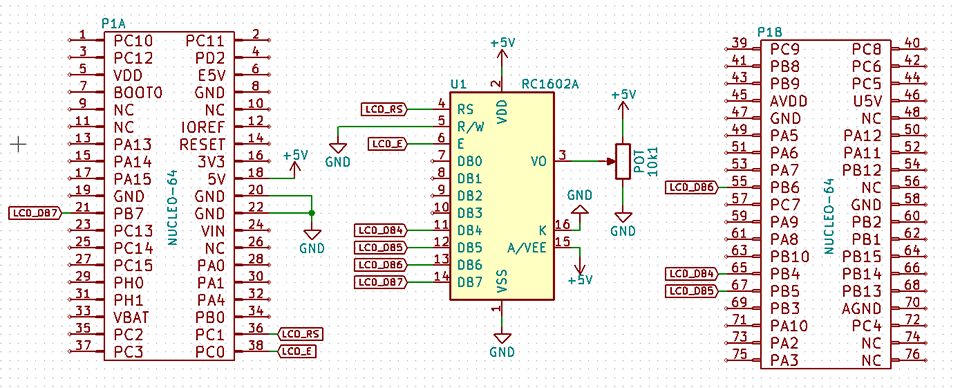
The connection diagram looks as follows:
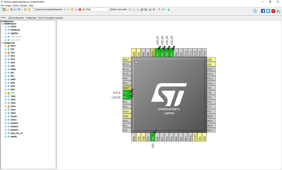
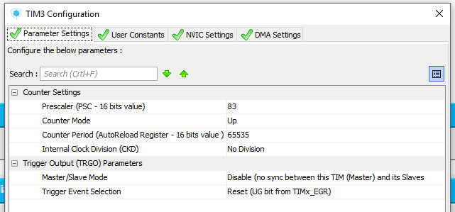
and the STM32CubeMX configuration
From the standpoint of measuring refresh time, we’re interested in the time to send all commands and data to the display so that the test text appears. By tying the RW pin to ground, we put the display into continuous write mode. In this mode you must adjust the wait time between sending subsequent data so that it is longer than the processing of the previous byte. First I’ll do this using the simplest HAL_Delay(), which is offered by ST’s library.
//
// Write byte to LCD
//
void LCD_WriteByte(uint8_t data)
{
	SET_LCD_E;
	LCD_SetDataPort(data >> 4);
	RESET_LCD_E;

	SET_LCD_E;
	LCD_SetDataPort(data);
	RESET_LCD_E;

	HAL_Delay(1); // <<--- wait for data processing
}
The test code I will base on looks as follows:
while (1)
{
	// Measurement start
	LCD_Cls();
	LCD_Locate(0,0);
	LCD_String(" STM32 + HD44780");
	LCD_Locate(0,1);
	LCD_String("www.msalamon.pl ");
	// Measurement end
	HAL_GPIO_TogglePin(LED_GPIO_Port, LED_Pin);
	HAL_Delay(500);
}
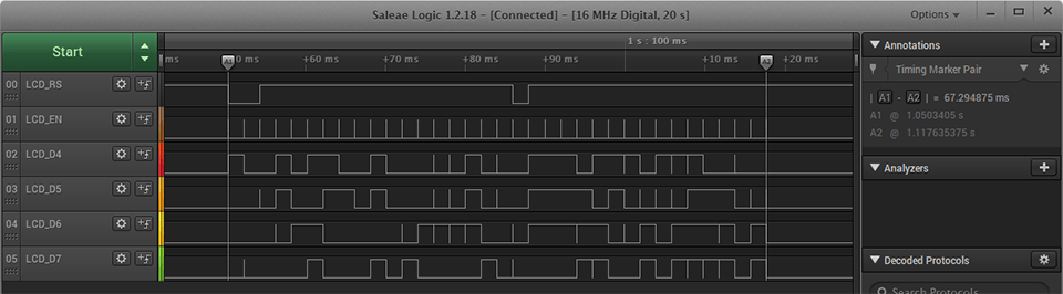
Unfortunately the HAL_Delay() function works with a minimum resolution of 1 ms, which is the time base for the entire STM32HAL library. For the display this is relatively long, hence the result is poor. You can clearly see the refresh on the screen because it’s simply too slow. The entire test refresh procedure takes as much as 67.29 ms! That’s more than three times longer than what the human eye needs to be fooled and not notice the refresh. Because of this you can also see how the second line of characters flickers badly.
We need to speed this up! Unfortunately ST’s library doesn’t have any delay function with finer resolution. What now? I’m ending the post. You can’t do it on STM32 – Arduino is better 🙁
I WAS JOKING!
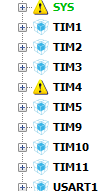
The MCU used in the example (like every STM32) has plenty of hardware timers. Why let them sit and gather dust? I’ll use one for the delay. Which one? For now I won’t dive into the intricacies of timers and will quickly go over the configuration. Today the random choice fell on TIM3 with internal clocking. The Delay we need should operate with 1 µs resolution, so using the magic formula we end up with a required clock of 1 MHz. Using another magic formula, with an 84 MHz clock, to supply 1 MHz to TIM3 I need to set the prescaler to 83. I’ll set the counting direction to Up, a CounterPeriod to the maximum value, i.e., 65535 (16‑bit timer). I’ll leave other settings at defaults. I won’t enable any interrupts or other bells and whistles for the timer. After setting it up, I regenerate the project code.
For clarity I wrote the delay code in separate files – delays.c and delays.h.
void Delay_us(uint16_t us)
{
  htim3.Instance->CNT = 0;
  while(htim3.Instance->CNT <= us);
}
After setting the delay between sending bytes to 120 µs, a problem appeared in the form of cutting off the beginning of the frame. The issue lies in processing the previously written cls and locate commands. By shortening the data transfer I also had to extend the wait after commands, as their execution takes a bit longer than accepting data. I tested various numbers of microseconds, but quickly approached a value of 1 ms.
//
// Write byte to LCD
//
void LCD_WriteByte(uint8_t data)
{
	SET_LCD_E;
	LCD_SetDataPort(data >> 4);
	RESET_LCD_E;

	SET_LCD_E;
	LCD_SetDataPort(data);
	RESET_LCD_E;

	// HAL_Delay(1);
	Delay_us(120); //<<--- wait for data processing
}

//
// Write command to LCD
//
void LCD_WriteCmd(uint8_t cmd)
{
	RESET_LCD_RS;
	LCD_WriteByte(cmd);
	Delay_us(1000);//<<--- wait for command processing
}
Result? It’s definitely better. You can’t see “writing” across the screen, so it’s acceptable. Execution time? 7.14 ms, which means we can squeeze out about 140 Hz max. Success!

In the next post I’ll handle the busy flag. I’ll see how much further I can shorten the frame transmission 😉
The second part of the post is >>here<<.
If you like the display, you can buy it in various versions in my store.
The complete code from this series of posts is on my GitHub: link
To end this post, I encourage discussion in the comments about handling the LCD on STM32. Do you think I made a mistake somewhere? Do you have an interesting idea for what can be improved? Share it in a comment! Remember that the discussion should be courteous and in accordance with the rules of the Polish language.
Podobne artykuły


0 Comments