I remember when the Nokia N95 hit the market, which was a huge technological leap. It had a built-in accelerometer thanks to which, among other things, the interface would change orientation by itself. Today this probably doesn’t impress anyone anymore, but in 2007 an app with lightsaber sounds triggered by
waving the phone blew my mind. Today accelerometers are present in many devices. And not just accelerometers, because these are powerful and extensive IMU (Inertial Measurement Unit) units having not—like an accelerometer—3 degrees of freedom (acceleration along the X, Y and Z axes), but 6, 9, and in combination with a barometer even 10 degrees of freedom, also denoted as XDoF (X – number of degrees).
MPU6050 Accelerometer
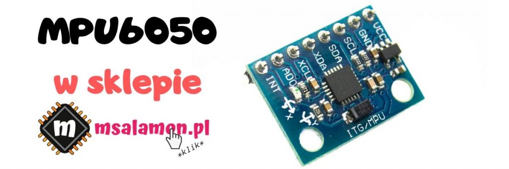
Today’s patient will be the MPU6050 from InvenSense. It’s a 6‑degree‑of‑freedom IMU. Thanks to the built‑in gyroscope it extends the basic 3 degrees from the accelerometer by another 3 from the gyroscope. Thus, with it we can measure acceleration (accelerometer) and angular velocity (gyroscope) around each axis. This sensor is a MEMS (Microelectromechanical System), which means that in addition to electronics it also contains mechanical (moving) elements in its structure.
Parameters
The chip is very small. Its dimensions are only 4 x 4 x 0.9 mm, which makes it ideal for use in small devices such as smartphones, watches or drones. The MPU6050 has six 16‑bit converters built in, one for each measured value. The measured acceleration and rotational speed ranges are set in software. The accelerometer can measure within ±2g, ±4g, ±8g or ±16g, while the gyroscope within ±250, ±500, ±1000, ±2000°/sec (aka dps – degrees per second).
The chip has a built‑in 1024‑byte FIFO queue. Thanks to this, you can read from the chip less often and save more power if the device is battery‑powered.
To offload the microcontroller that will fetch data from the accelerometer, the MPU6050 has a built‑in ‘motion processor’ DMP (Digital Motion Process). This unit allows, for example, motion detection or free‑fall detection as well as many other useful things. Unfortunately, the user has no direct access to it. Even the documentation doesn’t say much about the DMP. On the Internet there are many results of reverse engineering that allow you to use part of the DMP’s features. To fully enjoy the motion processor assistance, you should use the libraries provided by InvenSense.
As for electrical parameters, the supply voltage tolerated by the chip is in the range 2.375–3.46 V. The interface through which you can talk to the IMU is I²C. Interestingly, the chip itself allows the I²C logic to operate at voltages as low as 1.71 V. However, Chinese modules do not allow this—all of the chip’s power pins are connected to 3.3 V.
An interesting tidbit is the built‑in temperature sensor, which we can simply use.
Another interesting thing is the ability to connect additional I²C devices to the MPU6050. The chip can communicate with other devices and collect data from them. You can use, for example, an external magnetometer/compass and thus add another three degrees of freedom. We can simultaneously handle four different I²C devices via the MPU6050’s external I²C lines.
More data such as current consumption under various conditions and configurations can be found in the documentation:
MPU60X0 Datasheet.pdf
Schematic and configuration
Today I’ll use the Nucleo board with the STM32F401RE microcontroller.
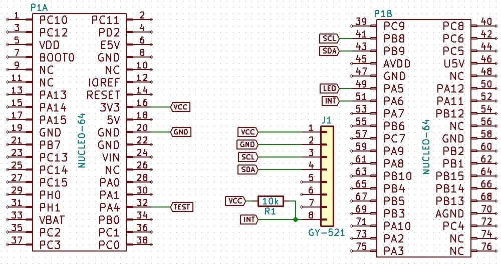
My module with the MPU6050 is the popular GY-521. The wiring diagram is as follows:
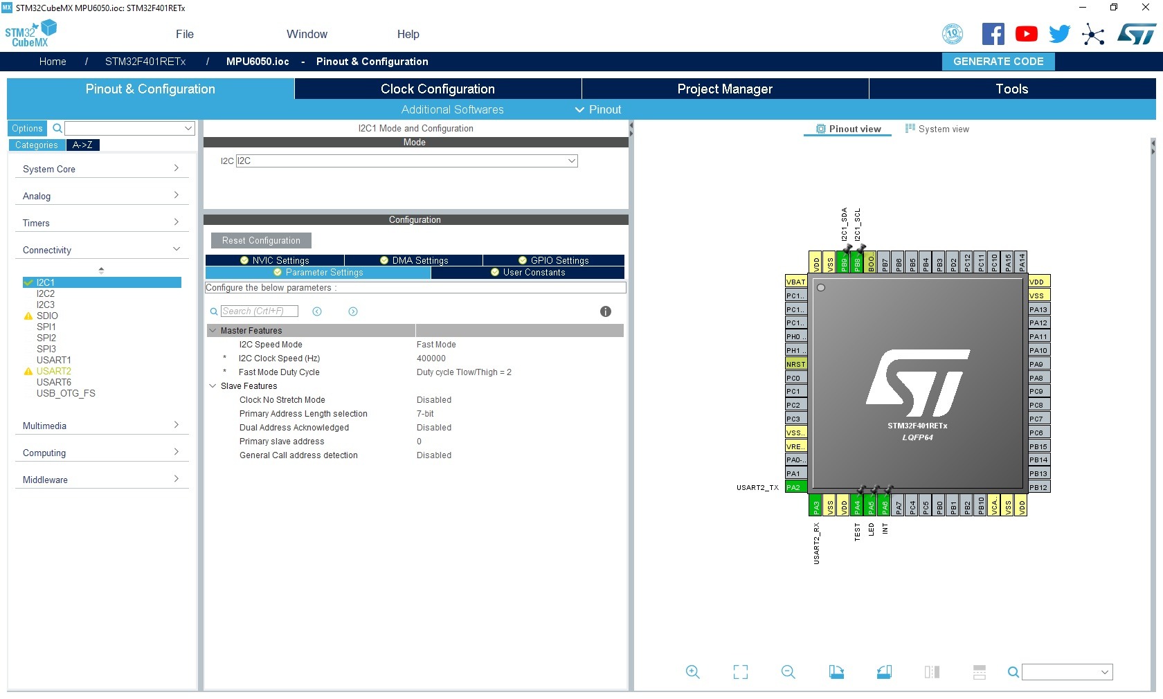
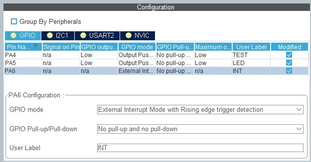
The Cube configuration is simple—I²C and an external interrupt on pin PA6. I²C can be sped up to 400 kHz. I pulled the interrupt down to ground with an external resistor, and in the configuration I chose no internal pull‑up. Of course, you can use the internal ones. UART, LED and TEST are for testing and debugging purposes.
Code
The code can basically be divided into 4 sections:
- Accelerometer configuration
- Reading measured values
- Interrupt configuration
- Hidden DMP functions
In the configuration part there’s the standard device initialization function.
void MPU6050_Init(I2C_HandleTypeDef *hi2c);
It resets the accelerometer to default values, sets the clock source, and sets the measurement ranges for acceleration and angular velocity to ±2g and ±250°/sec.
Besides that, a number of functions handle configuration. The names really speak for themselves. You can reset the MPU6050, set the clocks, put the individual sensors to sleep or disable them. If needed, you can also increase the measurement range of the accelerometer and gyroscope.
//
// PWR_MGMT_1
//
void MPU6050_DeviceReset(uint8_t Reset);
void MPU6050_SetClockSource(uint8_t Source);
void MPU6050_SetSleepEnabled(uint8_t Enable);
void MPU6050_SetCycleEnabled(uint8_t Enable);
void MPU6050_SetTemperatureSensorDisbled(uint8_t Disable);

//
// PWR_MGMT_2
//
void MPU6050_SetLowPowerWakeUpFrequency(uint8_t Frequency);
void MPU6050_AccelerometerAxisStandby(uint8_t XA_Stby, uint8_t YA_Stby, uint8_t ZA_Stby);
void MPU6050_GyroscopeAxisStandby(uint8_t XG_Stby, uint8_t YG_Stby, uint8_t ZG_Stby);

//
// Measurement scale configuration
//
void MPU6050_SetFullScaleGyroRange(uint8_t Range);
void MPU6050_SetFullScaleAccelRange(uint8_t Range);
Probably the most important part from the user’s point of view is reading data from the accelerometer. I prepared several functions returning data in different variants. Functions with the RAW suffix return exactly what’s in the registers. The Scaled functions return values scaled to the selected maximum range, i.e., directly in units of gravitational acceleration, angular velocity in degrees per second, or degrees Celsius. The last function returns Pitch and Roll, i.e., in short, the tilt around the Y and X axes with respect to the Earth. I have one note regarding temperature. In my opinion the MPU6050 slightly overestimates the readings by about 3–4ºC. However, I didn’t modify the formula provided by the datasheet.
int16_t MPU6050_GetTemperatureRAW(void);
float MPU6050_GetTemperatureCelsius(void);

int16_t MPU6050_GetAccelerationXRAW(void);
int16_t MPU6050_GetAccelerationYRAW(void);
int16_t MPU6050_GetAccelerationZRAW(void);
void MPU6050_GetAccelerometerRAW(int16_t* x, int16_t* y, int16_t* z);
void MPU6050_GetAccelerometerScaled(float* x, float* y, float* z);

int16_t MPU6050_GetRotationXRAW(void);
int16_t MPU6050_GetRotationYRAW(void);
int16_t MPU6050_GetRotationZRAW(void);
void MPU6050_GetGyroscopeRAW(int16_t* x, int16_t* y, int16_t* z);
void MPU6050_GetGyroscopeScaled(float* x, float* y, float* z);

void MPU6050_GetRollPitch(float* Roll, float* Pitch);
In the interrupt configuration section, a significant part is taken by functions concerning the INT pin. You can choose, for example, the level with which it signals an interrupt and how the interrupt flag is cleared. The accelerometer offers three interrupts as standard:
- FIFO overflow
- I²C Master interrupt
- Data ready for reading
I haven’t dealt with the FIFO for now. Same for the I²C Master function. The DataReady interrupt can be said to be almost always active because the accelerometer by default continuously generates data.
//
// Setting INT pin
//
// INT_PIN_CFG register
void MPU6050_SetInterruptMode(uint8_t Mode);
void MPU6050_SetInterruptDrive(uint8_t Drive);
void MPU6050_SetInterruptLatch(uint8_t Latch);
void MPU6050_SetInterruptLatchClear(uint8_t Clear);
// INT_ENABLE register
void MPU6050_SetIntEnableRegister(uint8_t Value);
void MPU6050_SetIntDataReadyEnabled(uint8_t Enable);
// INT_STATUS register
uint8_t MPU6050_GetIntStatusRegister(void);
So what the heck do we need this interrupt for? Well, the MPU6050 has a built‑in DMP which is not described in the sensor documentation nor in the register map. Probably because InvenSense provides its extensive driver for this purpose. The Internet, of course, never sleeps and has figured out a few things. Thanks to that we have easy access to basic motion processor functions.
Digital Motion Process
The DMP gives us three very useful interrupts. These are:
- Free‑fall detection
- Motion detection
- No‑motion detection
The chip can process the sensor data itself and assert the appropriate interrupt. I’ve included all three in the library. There are also a few options around them to set.
//
// Motion functions - not included in documentation/register map
//
uint8_t MPU6050_GetMotionStatusRegister(void);

void MPU6050_SetDHPFMode(uint8_t Dhpf);
// INT_ENABLE register
void MPU6050_SetIntZeroMotionEnabled(uint8_t Enable);
void MPU6050_SetIntMotionEnabled(uint8_t Enable);
void MPU6050_SetIntFreeFallEnabled(uint8_t Enable);

void MPU6050_SetMotionDetectionThreshold(uint8_t Threshold);
void MPU6050_SetMotionDetectionDuration(uint8_t Duration);

void MPU6050_SetZeroMotionDetectionThreshold(uint8_t Threshold);
void MPU6050_SetZeroMotionDetectionDuration(uint8_t Duration);

void MPU6050_SetFreeFallDetectionThreshold(uint8_t Threshold);
void MPU6050_SetFreeFallDetectionDuration(uint8_t Duration);
The first function reads the status register responsible for detected motion. It contains information about which direction of motion triggered the MotionDetect interrupt. Maybe someone will find it useful. At the moment I don’t see an application for it in my case.
//
// Not documented
// Register 91 - Motion Status
//
#define MPU6050_MOTION_MOT_XNEG_BIT 7
#define MPU6050_MOTION_MOT_XPOS_BIT 6
#define MPU6050_MOTION_MOT_YNEG_BIT 5
#define MPU6050_MOTION_MOT_YPOS_BIT 4
#define MPU6050_MOTION_MOT_ZNEG_BIT 3
#define MPU6050_MOTION_MOT_ZPOS_BIT 2
The second function sets the high‑pass filter for the DMP. I didn’t notice any effect on the interrupts’ behavior. Maybe someone knows more details about this filter? I recommend setting it to the value MPU6050_DHPF_5 as I did.
And then there are the functions responsible for event detection. First, you can use them in two ways: with the INT pin, or without it by polling the interrupt status cyclically. I don’t see a reason to poll the MPU for interrupt status. It’s better to have this handled in hardware, which you enable with the appropriate functions.
Next come the settings for the conditions under which an interrupt occurs. Threshold is the change in acceleration at which the internal counter starts counting. Duration is the value of that counter after which the interrupt will be asserted. If the acceleration value drops below the threshold before the interrupt, the counter resets.
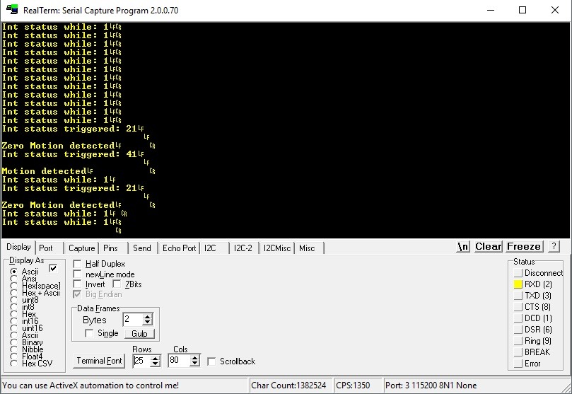
The threshold is expressed in mg (milli‑g), and the value written is multiplied by 2. The duration is in milliseconds. So by writing Threshold = 2, Duration = 5 into the MotionCapture registers, the interrupt will occur 5 milliseconds after exceeding a 4 mg difference compared to the rest state. It may sound a bit complicated, so I recommend experimenting. I tested all the interrupts and they definitely work. A tap on the desk triggers the appropriate Motion and ZeroMotion.
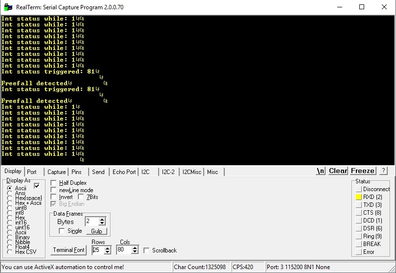
Dropping the sensor will generate the Freefall interrupt.
Gyroscope drift
Unfortunately, IMU chips, like everything in electronics, are imperfect. You can feel this most on the gyroscope. It has something called drift, i.e., it constantly indicates some value even though it’s standing still. This can be seen in the terminal screenshot below.
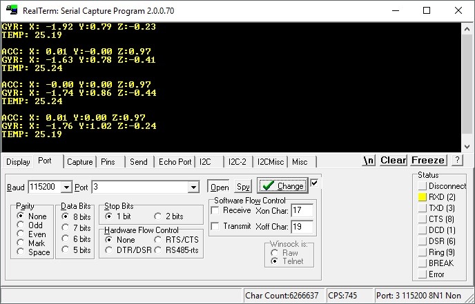
MPU6050 I have on my desk has quite a large drift on the X axis. From this it follows that in about 180 seconds it makes a full rotation around X. I’ll tell you, I’m looking at it and to me it’s not spinning on this desk at all 🙁
One way to minimize this error is filtering. The most effective here is the Kalman filter, which will have a separate post.
Summary
MEMS systems are very interesting creations. Thanks to them you can easily bring “mechanical quantities” into the world of electronics and thus easily process them. Without accelerometers there would be no drones or VR glasses.
Thanks to the built‑in DMP you can save many CPU cycles or even use interrupts for cool purposes. I see, for example, putting a smartwatch to sleep and waking it based on detected motion/no‑motion. There are certainly many other applications for this kind of detection. Share your ideas in the comments.
If you like the chip, you can buy it in my store.
You can find the code on my GitHub as usual: link
If you noticed any mistake, disagree with something, would like to add something important, or simply feel like discussing this topic, write a comment. Remember that the discussion should be polite and consistent with the rules of the Polish language.
Podobne artykuły





0 Comments