Can you imagine life without navigation? I, for one, can’t. Location devices are, for me, one of the best inventions. All the more so because we have them in our pockets. We can also add a GPS receiver to our electronic projects. See how simple it is!
How does GPS work?
In a very brief nutshell. There are 31 satellites orbiting the Earth whose flight parameters are precisely known. They are at an altitude of about 20 thousand kilometers above the Earth’s surface. The orbits of these satellites are circular, and it takes them exactly 11 hours and 58 minutes to orbit the planet. There are 28 satellites permanently active. The rest are test units or simply switched off.
These satellites transmit signals on two frequencies: 1575.42 MHz and 1227.6 MHz. Based on the signals received from the satellites, the receiver is able to calculate our position.
But how? For example, knowing the propagation speed of a radio wave, we can determine the time it takes for radio signals to reach the receiver. The transmitted signal contains several pieces of information useful for locating, including satellite positions, so on this basis we can determine our coordinates. The more satellites are visible, the greater the positioning accuracy.
You can find a very good description of the entire system on the RS Elektronika YouTube channel. I highly recommend taking a look there.
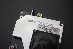
NEO6MV2 GPS receiver
The manufacturer of the GPS module is u-blox. The NEO-6 receivers are a whole family of chips. The exact one I’m dealing with today is the NEO-6-M-0-001, and the module it’s mounted on is called NEO6MV2.
The documentation lists a few interesting details about the receiver itself. The most important are:
- Maximum number of satellites: 50
- Cold start: 27 seconds
- Warm start: 27 seconds
- Hot start: 1 second
- Assisted start (A-GPS): under 3 seconds
- Positioning accuracy: 2.5 meters
- Maximum position update rate: 5 Hz (1 Hz by default)
- Interfaces: UART, USB, SPI
The complete module has a status LED, EEPROM to store configuration, and a backup battery that helps with warm/hot starts.
Only the UART interface is brought out to the NEO6MV2 module header. It is the primary form of communication. The module also has a µFL connector for attaching an antenna. You can buy the module with an antenna included. It’s usually a small antenna that works pretty well outdoors, but is definitely worse indoors. I had to wait a long time with the antenna stuck to the window.
After powering up, the device immediately transmits NMEA messages on the RX pin. What is this enigmatic acronym?
NMEA
NMEA (National Marine Electronics Association) is a communication protocol between marine electronic devices. Interesting, right? However, it is the standard when it comes to GPS devices.
Data comes as ASCII-encoded messages. They are therefore somewhat human-readable. A single message can contain a maximum of 82 characters. Each sentence begins with a dollar sign ($), then there is the sentence identifier, followed by subsequent data separated by commas. The sentence ends with the character sequence “\n\r”.
For the GPS system all messages start with “$GP”. Dozens of message types are defined, but for GPS I found 19 useful ones, which are described here: http://aprs.gids.nl/nmea/
In the default configuration, the NEO-6 outputs only a few of them:
- $GPRMC – recommended message, minimum navigation data set
- $GPVTG – course and speed
- $GPGGA – GPS navigation data determined in the receiver
- $GPGSA – DOP (dilution of precision) coefficients
- $GPGSV – PRN numbers and positions of potentially visible satellites and signal strength
- $GPGLL – geographic position
Some data is repeated across several messages. Of course, you can edit what the receiver outputs on the UART interface. You can use the UBX protocol for this, but it’s easier to connect the module to a computer and use the u-center application. It’s a powerful tool that will, of course, read data from the NEO-6 module, but also configure it freely, and even update the module’s firmware. To connect a module that only has UART, you can use a UART<->USB converter, which you can buy in my store.
Connections and Cube configuration
Today I’ll use the Nucleo F401RE board. For firmware configuration and programming I used STM32CubeIDE version 1.0.2 and the HAL libraries F4 1.24.1.

Allow me, perhaps for the first time on the blog, to skip the schematic. Connecting the module is really simple and boils down to powering it and wiring the TX and RX pins to the Nucleo. I powered the GPS board from 5V, and connected communication to UART1:
- TX GPS to RX Nucleo on PA10
- RX GPS to TX Nucleo on PA9
I also brought out a test pin for timing measurements 🙂
Now Cube. In addition to the standard Nucleo settings such as HCLK = 84 MHz, set UART1 to 9600 baud 8n1. Also enable the global interrupt for UART1 in the NVIC Settings tab.
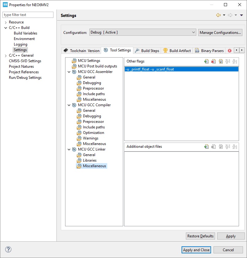
You can now generate the project 🙂 After generation, it’s very important to add -u_printf_float to the linker options because we’re going to use it.
Code
I haven’t written anything based on UART reception for a long time. But I managed hehe 🙂 This time I opted for receiving single characters in an interrupt so as not to blockingly wait for incoming data. Step by step.
First, we should initialize the library. I created a struct variable to store all the data related to our module. Thanks to this structure, you can connect several independent NEO-6 modules because it contains a pointer to the UART and its own receive and working buffer for it.
typedef struct
{
	//
	// UART stuff
	//
	UART_HandleTypeDef *neo6_huart;
	uint8_t UartBuffer[GPS_UART_BUFFER_SIZE];
	uint8_t UartBufferHead;
	uint8_t UartBufferTail;
	uint8_t UartBufferLines;

	uint8_t WorkingBuffer[GPS_WORKING_BUFFER_SIZE];

	//
	// Time and Date
	//
	uint8_t Hour;
	uint8_t Minute;
	uint8_t Second;
	uint8_t Day;
	uint8_t Month;
	uint8_t Year;

	//
	// Position
	//
	double Latitude;
	char LatitudeDirection;
	double Longitude;
	char LongitudeDirection;
	double Altitude;

	//
	// Speed
	//
	double SpeedKnots;
	double SpeedKilometers;

	//
	// Satelites parameters
	//
	uint8_t SatelitesNumber;
	uint8_t Quality; // 0 - no Fix, 1 - Fix, 2 - Dif. Fix
	uint8_t FixMode; // 1 - no Fiz, 2 - 2D, 3 - 3D
	double Dop; // Dilution of precision
	double Hdop; // Dilution of precision for flat coords
	double Vdop; // Dilution of precision for height

}NEO6_State;
Initialization therefore fills the structure with initial data, assigns the UART for the receiver, and starts listening on the serial interface.
void NEO6_Init(NEO6_State *GpsStateHandler, UART_HandleTypeDef *huart);
Let me discuss how the STM32 acquires all the data from the GPS receiver. As you remember, the NEO-6 sends data by itself, once per second by default. The UART interrupt is set for every single received byte. Why? We’re never sure how many characters will arrive. Besides, this way it’s easier to control the moment when the end of the message arrives by recognizing the ‘\n’ character.
Receiving a character is handled in the NEO6_ReceiveUartChar function, which should be placed in the UART receive-complete interrupt.
/* USER CODE BEGIN 4 */
void HAL_UART_RxCpltCallback(UART_HandleTypeDef *huart)
{
  if(huart == GpsState.neo6_huart)
  {
    NEO6_ReceiveUartChar(&GpsState);
  }
}
/* USER CODE END 4 */
Let’s look inside this function. It operates on the receive buffer from the GPS data structure. This is a circular/ring buffer with no beginning or end. New data is appended at the next position in the buffer, and consumed data is removed from the “start”. Meanwhile, that start and end keep moving depending on what is being done on the buffer.
As overflow handling, I chose to drop incoming data. Fortunately, by setting a sufficiently large buffer, and as long as the microcontroller isn’t blocked on some task, such choking shouldn’t occur. It’s good to set the buffer to a value of 2x the longest message. As we know from the NMEA standard, it will be 81 characters at most, so the minimum buffer is 162 bytes. I set 256 because it’s such a nice, round number.
Okay. What happens when there is space? Three conditions are checked:
- Character 0x0D, i.e. <CR> or ‘\n’. Do you remember what’s at the end of an NMEA sentence? Among other things, this character. When it’s received, I increment the variable that tells how many messages are waiting to be analyzed and, of course, write this character to the ring buffer.
- Characters 0x0A and 0x00. 0x0A is <LF> or ‘\r’. One terminating character is enough, so I drop this one. Same with zero. It carries no information in ASCII communication. On the other hand, it also shouldn’t happen that we get a zero from the module, so it could be ignored in considerations…
- The remaining characters are simply added to the buffer.
At the very end I re-enable UART RX listening for one character.
There is a function called
void NEO6_Task(NEO6_State *GpsStateHandler);
which you must place in the program’s main loop. It checks whether a complete message has already arrived. If so, it fetches the whole thing from the ring buffer into the working buffer and analyzes (parses) the message. How can such a message be parsed?
Parsing NMEA
Two (three) functions are very useful for this:
- strcmp – comparing C-strings
- strtok – splitting a string into smaller chunks by a “token”
- strtoke – a modification of strtok I’ll get to in a moment
Notice one characteristic thing in NMEA. Data is always separated by a comma and each piece of information has its defined place. An example of what the module prints after getting a fix:
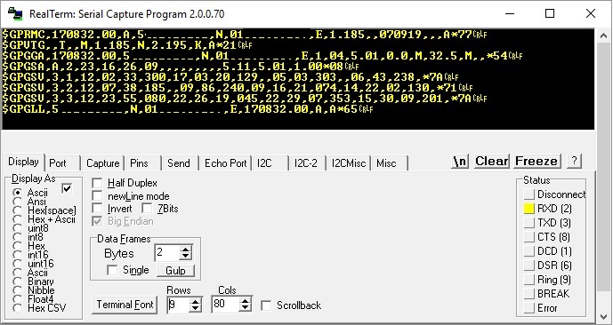
There’s also a small piece after the asterisk which is a checksum. I’ll skip it during parsing. I trust I’m receiving correct data.
It would be good to leverage those commas. For this, the strtok function is perfect.
char *strtok(char *s, const char *delim);
How do you use it? It takes as arguments a pointer to the string to be split and the token by which it will split. Our token is a comma.
What does it do with that comma? It inserts 0x00 in its place, i.e. the end-of-C-string character, and returns a pointer to this modified string. Now you can easily operate on it.
Alright, but did the rest of the buffer just disappear or what? What about the characters after the comma?!
Well, the next call to strtok will return a pointer to the next string, i.e. the one after the last found token, meaning the characters between the first and second comma. It’s important that you don’t pass a pointer to the next string as the first argument now. To continue splitting the same buffer, you should now pass NULL as the first argument.
An example straight from the code. To extract the NMEA message header I use strtok. Let’s say the message looks like this:
$GPRMC,081836,A,3751.65,S,14507.36,E,000.0,360.0,130998,011.3,E*62
char* ParsePoiner = strtok((char*)GpsStateHandler->WorkingBuffer, ",");
I passed a pointer to the working buffer which contains the full NMEA message. As the token, of course, ‘,’. Under ParsePointer we now have the string “$GPRMC”.
Next call
ParsePoiner = strtok(NULL, ",");
Will result in ParsePointer now being the string “081836”, representing the time. We can now convert it to a number and assign it to appropriate variables.
Let’s call strtok once again.
ParsePoiner = strtok(NULL, ",");
Now ParsePointer is “A”. We keep doing this until we obtain all the data, operating on those split strings with functions that convert ASCII to float, for example. And that’s the whole magic of parsing this way. I hope you get it.
The strtok trap
There’s no rose without thorns. A big thorn is this super function strtok itself. Why? Notice that some data fields are empty, i.e. there are two commas in a row. Especially if there is no fix. Why is this dangerous?
Well, the strtok function does not return empty strings. Instead, it returns the next string with some content. As a result, if some data is missing in the sequence of tokens, our parsing gets broken… You can write some smarter parsing logic, but… you can also write a better token function. One that will return an empty string.
I found an implementation of such a function on the site loved by programmers with problems.
The function is called strtoke and works exactly like standard strok except that it can return an empty string. You can safely replace all calls with this improved one. Now empty fields won’t be skipped. Success!
Result
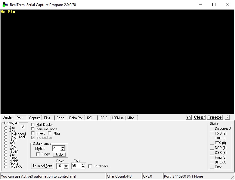
The sample code I wrote prints to UART2 the data it received from the GPS on UART1. However, it doesn’t always print—only when the module has a fix.

Let’s also look at the logic analyzer to see how the interrupts and data parsing are doing.
Receiving all messages from the NEO-6 looks like this.
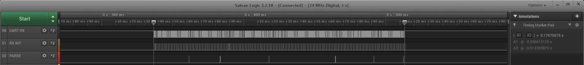
The entire frame the module sends is over 100 ms. This one doesn’t have a fix. It won’t lock on my desk… Adding data after getting a GPS signal, this frame will be a bit longer.
As you can see in the second row there are lots of interrupt calls for character reception. They are triggered often so they look serious. How much do they knock the microcontroller out of its normal operation?

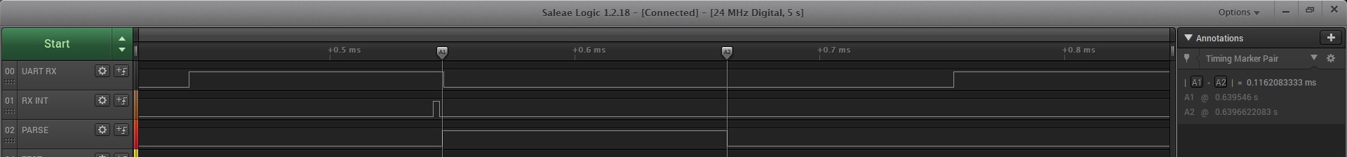
The interrupt lasts about 2.8 µs. Considering that this time also includes handling the test GPIO pin, that’s very little. Such an interrupt is invoked every exactly 1.04 ms when the next character arrives.
On an even lower level you can see a few spikes. I marked the moments of data parsing here.
Parsing, i.e. splitting, searching strings, and converting data takes about 100 µs.
Summary
Handling GPS is very easy. Just a few tricks are enough to fully enjoy the messages transmitted by the NEO-6 module. Reception and data processing are very fast. Also remember that the times I presented relate to an HCLK frequency of 84 MHz.
Where can you use such a GPS? Lately I see an application for it in a measurement device with LoRa communication. We kind of know where the device is, but when producing several of them, we don’t have to worry about manually entering the location. A cool solution was recently suggested to me by one of the readers. It was a measurement drone. It performs air quality measurements and automatically saves them to an SD card together with the measurement location. Great use case.
An additional advantage of using GPS is the accurate time. You can use it to synchronize the RTC or even consider removing the clock from the device altogether.
GPS receivers are everywhere these days. For example in smartphones or cars. Even drones have GPS, which, for example, assists in piloting the machine.
You can find the full project along with the library on my GitHub as usual: link
If you noticed any mistake, disagree with something, would like to add something important or simply feel like discussing the topic, leave a comment. Remember that the discussion should be polite and in accordance with the rules of the Polish language.
Podobne artykuły


0 Comments