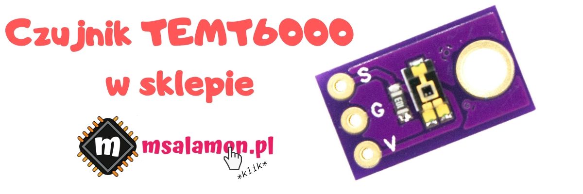
Measuring light intensity is common in our everyday life. Probably everyone has an auto dimming/brightening screen feature in their smartphone. It is based precisely on measuring the light intensity around the device. The measurement is performed continuously while the phone is unlocked. Today I will focus on how we can measure this parameter using three different sensors. Will they produce similar readings?
Light measurement – today’s heroes
I will measure light with three sensors: BH1750, MAX44009 and TEMT6000.
You can download the datasheets for these chips here:
BH1750FVI Datasheet
MAX44009 Datasheet
TEMT6000 Datasheet
Schematic and Cube configuration

For today’s task I took the Nucleo with STM32F401RE board. Since I am once again working with ready-made Chinese modules, the schematic is quite simple.
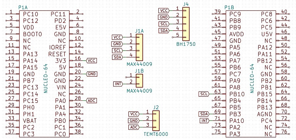
Two of today’s sensors communicate via the I²C interface. Additionally, one can assert interrupts, so I will assign a suitable pin for it. The third sensor outputs an analog value, so we need to prepare one of the analog inputs. The final pinout looks like this.
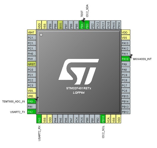
I configure I²C at 400 kHz. The interrupt will need to react to the falling edge. I will discuss the ADC configuration later with the respective sensor.
BH1750
The first tested sensor is the low-power BH1750 from ROSH Semicondutor(
BH1750FVI Datasheet
). You can talk to it over the I²C interface with a maximum clock frequency of 400 kHz. It has a built-in ADC that converts the measured light intensity into a digital value. Its measurement range is 1 – 65535 lux. The sensor allows calibration of measurement sensitivity. Thanks to this it can detect as low as 0.11 lux. This setting can also be adjusted to the covering material, e.g. glass. You should know the value of the light transmission through that material. See the datasheet for details.
The sensor can operate in several modes:
- Continuous high resolution (1 lx)
- Continuous high resolution 2 (0.5 lx)
- Continuous low resolution (4 lx)
- One-time high resolution (1 lx)
- One-time high resolution 2 (0.5 lx)
- One-time low resolution (4 lx)
The manufacturer recommends using the high-resolution mode with a 1 lux resolution. Allegedly it handles interference well. I also like it because the value in the measurement registers will not need to be converted. In continuous mode the measurement is performed cyclically at 120 ms or 16 ms intervals depending on the chosen mode. In manual mode, the conversion is triggered only once. You must then wait until the ADC finishes (120 ms for high-res and 16 ms for low-res) before you can read the measurement value. Unlike continuous operation, in manual mode the sensor automatically enters Power Down after the conversion where the current consumption is negligible (typ. 0.01 µA) compared to what is required for conversion (typ. 120 µA). You don’t have to wake the sensor manually. Just request a conversion.
The register table is basically not a register table. You communicate with the sensor using a set of commands without writing anything directly to its memory. Let’s move on to the code.
In the first step, the sensor should be initialized. In addition to passing a pointer to the I²C interface used, I reset the sensor and set its default measurement time value.
BH1750_STATUS BH1750_Init(I2C_HandleTypeDef *hi2c);
The following functions are used to reset the sensor and control the Power Down state
BH1750_STATUS BH1750_Reset(void);
BH1750_STATUS BH1750_PowerState(uint8_t PowerOn);
If you need to change the sensor’s sensitivity, use
BH1750_STATUS BH1750_SetMtreg(uint8_t Mtreg);
Set the mode in which the sensor is to operate with
BH1750_STATUS BH1750_SetMode(bh1750_mode Mode);
using an enum variable with predefined commands. This reduces the risk of mistakes.
typedef enum
{
	CONTINUOUS_HIGH_RES_MODE = 0x10,
	CONTINUOUS_HIGH_RES_MODE_2 = 0x11,
	CONTINUOUS_LOW_RES_MODE = 0x13,
	ONETIME_HIGH_RES_MODE = 0x20,
	ONETIME_HIGH_RES_MODE_2 = 0x21,
	ONETIME_LOW_RES_MODE = 0x23
}bh1750_mode;
If you will be using manual mode, you will need a function that triggers the conversion. In fact, it just sends the command to set the conversion mode because that’s what the sensor requires, but who would remember throughout the project which mode is used 😉
BH1750_STATUS BH1750_TriggerManualConversion(void);
And the most important one: the function to read the value measured by the sensor. Its usage should be straightforward.
BH1750_STATUS BH1750_ReadLight(float *Result);
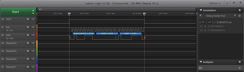
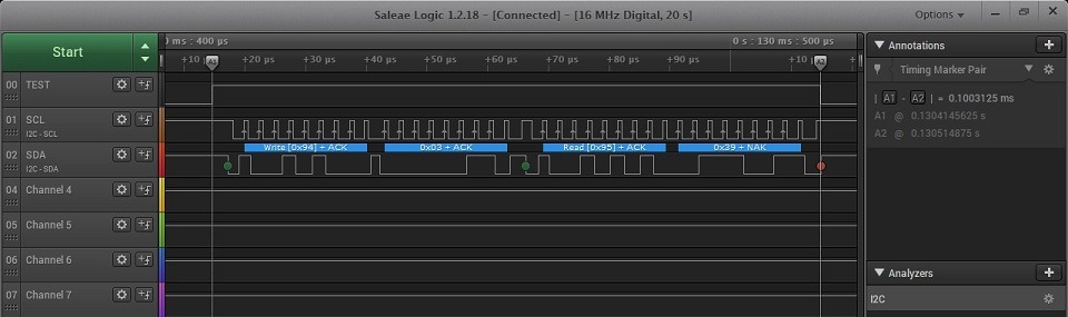
What does a read from the sensor look like? It’s enough to receive data directly from its address. Its address is at the same time the register from which the result is read. There’s no great philosophy here, hence the reading and value conversion are instantaneous. In high resolution 2 mode with 0.5 lux precision, it takes 0.28 ms for a 100 kHz I²C clock and 80 µs for 400 kHz.
100 kHz:
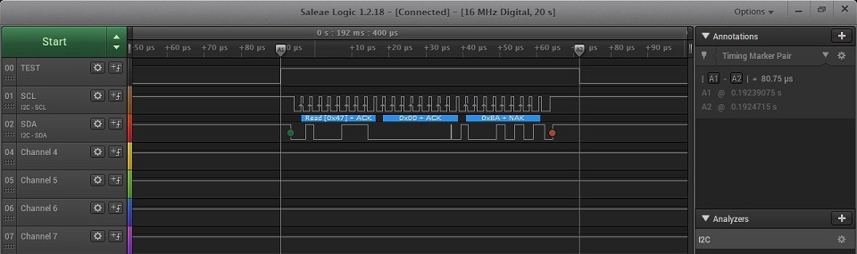
400 kHz:
Remember that if you want to use manual conversion, you must wait the appropriate time between requesting the measurement and reading it. Of course, the data can be read using DMA. Try to do it yourself 🙂
MAX44009
The next sensor today is the MAX44009 from Maxim Integrated (
MAX44009 Datasheet
). Like the BH1750, it has a built-in ADC and an I²C communication interface. It differs, among other things, in the way the result is encoded. It is stored in floating-point form with a 4-bit exponent and an 8-bit mantissa. I wrote about floating-point numbers here. The way the measurement value is stored allows you to read the result with different precision. You can read two registers and get a high-resolution result, or you can skip the second register, which contains the lower bits of the mantissa, and enjoy a faster result but with lower resolution.
Another difference is the INT pin, i.e. the ability for the chip to assert an interrupt to the microcontroller. The interrupt can be asserted after exceeding one of the configurable light intensity thresholds — upper or lower. At the same time, a minimum time the threshold must be exceeded is defined to decide whether to assert the interrupt. Of course, the thresholds can be set as a window. Importantly, the interrupt will be asserted even if it is operating in manual mode.
Because the MAX44009 is a bit more feature-rich, the library is more extensive. Initialization only assigns the I²C pointer:
MAX44009_STATUS MAX44009_Init(I2C_HandleTypeDef *hi2c);
Next are the sensor configuration functions. You can write the appropriate value to the register in one go, or use several convenient self-documenting functions that change only one function.
MAX44009_STATUS MAX44009_ReadConfigurationRegister(uint8_t *Config);
MAX44009_STATUS MAX44009_WriteConfigurationRegister(uint8_t Config);

MAX44009_STATUS MAX44009_ContinuousMode(uint8_t Enable);
MAX44009_STATUS MAX44009_ManualConfiguration(uint8_t Enable);
MAX44009_STATUS MAX44009_CurrentDivisionRatio(uint8_t Enable);
MAX44009_STATUS MAX44009_IntegrationTime(max44009_timer Timer);
Note the last function, which takes an enum as an argument:
typedef enum
{
	INTEGRATION_TIME_6_25_MS = 0x07, // Manual mode only
	INTEGRATION_TIME_12_5_MS = 0x06, // Manual mode only
	INTEGRATION_TIME_25_MS = 0x05, // Manual mode only
	INTEGRATION_TIME_50_MS = 0x04, // Manual mode only
	INTEGRATION_TIME_100_MS = 0x03, // This is a preferred mode for high-brightness applications
	INTEGRATION_TIME_200_MS = 0x02,
	INTEGRATION_TIME_400_MS = 0x01,
	INTEGRATION_TIME_800_MS = 0x00 // This is a preferred mode for boosting low-light sensitivity
} max44009_timer;
The most important part is of course reading the ambient light value. As I mentioned earlier, it can be done in two ways and I have included both.
MAX44009_STATUS MAX44009_ReadLightLowResolution(float *Result);
MAX44009_STATUS MAX44009_ReadLightHighResolution(float *Result);
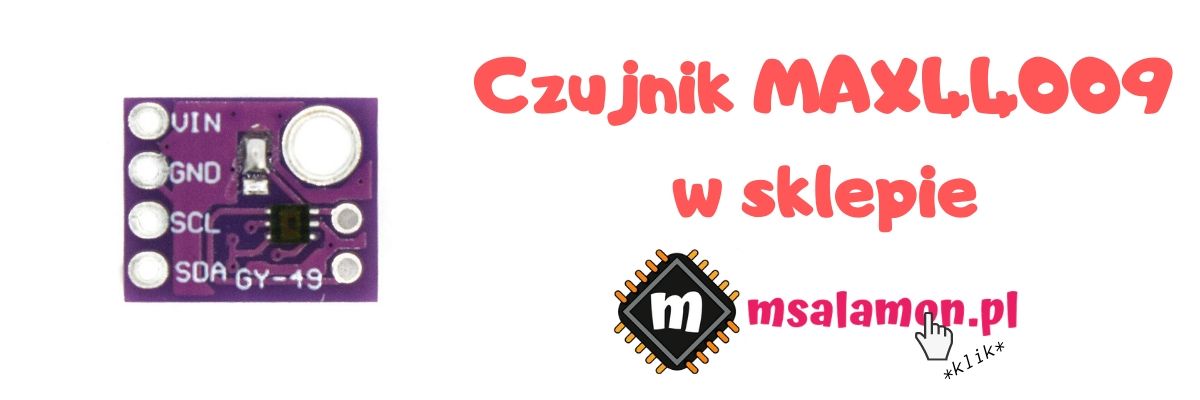
Here’s a little curiosity. The datasheet says: “If user wants to read both the Lux High-Byte register 0x03 and Lux Low-Byte register 0x04, then the master should not send a STOP command between the reads of the two registers. Instead a Repeated START command should be used.” What does this mean? The chip will increment the register address to be read on its own provided that after reading the first one, the master repeats a START sequence on the I²C bus. Unfortunately, when using the HAL function HAL_I2C_Mem_Read the microcontroller does not issue a START between consecutive bytes read. As a result, the sensor provides the value of register 0x03 twice instead of 0x04 in the second byte.
The simplest solution will be to simply call HAL_I2C_Mem_Read twice. Unfortunately, this costs a second addressing of the sensor and specifying the register from which to read.

If it turns out you need to shorten this time for some reason, a solution could be to use HAL_I2C_Master_Sequential_Receive_IT. Try to improve the readout with it 🙂
Finally, there are functions useful for interrupts.
MAX44009_STATUS MAX44009_ReadInterruptStatus(uint8_t *Status);
MAX44009_STATUS MAX44009_WriteInterruptEnable(uint8_t Enable);

MAX44009_STATUS MAX44009_SetUpperThreshold(float Threshold);
MAX44009_STATUS MAX44009_SetLowerThreshold(float Threshold);
MAX44009_STATUS MAX44009_SetThresholdTimer(uint8_t Timer);
The interrupt flag in the sensor is cleared automatically after reading the status register or disabling the interrupt. The boundary values that affect interrupt assertion are provided to and stored by the sensor in floating-point form with reduced resolution (4-bit exponent and 4-bit mantissa). Remember this limitation. The time requirement to assert the interrupt, passed in the argument, is in tens of milliseconds (value * 10 ms). So for a one-second setting, you should pass the value 100.
A few more numbers and plots.
100k low resolution:
400k low resolution:
100k high resolution:
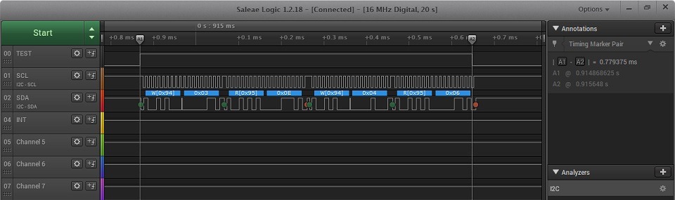

400k high resolution:
| Low resolution | High resolution | |
|---|---|---|
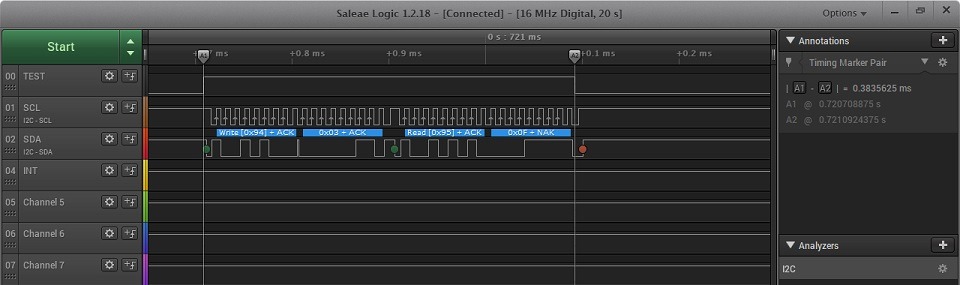
| 100 kHz | 0.38 ms | 0.78 ms |
| 400 kHz | 0.1 ms | 0.2 ms |
As you can see, the 400 kHz clock beats 100 kHz hands down. Even the high-resolution read at 400k is faster than the low-resolution read at 100k. Also remember that this readout isn’t optimal yet and can be sped up further.
I also tested interrupt thresholds. I set the threshold to 300 lux.
The interrupt is active low.
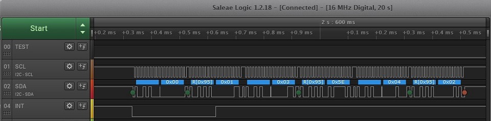
Works as expected 🙂
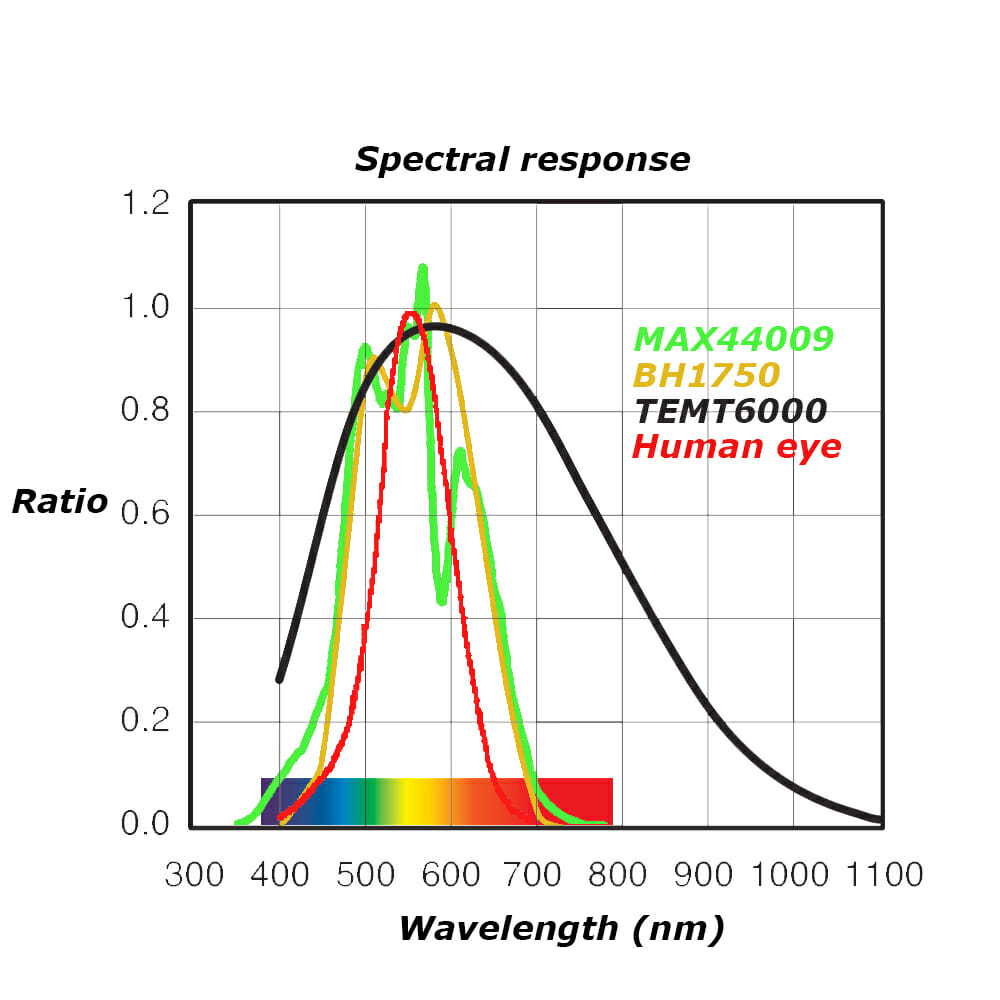
TEMT6000
The last light sensor discussed today is the TEMT6000 from Vishay. This time it is not a complete IC with a built-in ADC. This element is an NPN phototransistor. The current at its collector is proportional to the amount of incident light. The dependency is 1 µA = 2 lux, which is easy to convert.
We have to perform the sampling and calculations ourselves on the STM32. Fortunately, the MCU has a built-in 12-bit ADC, which makes things easier. The Chinese module has a resistor in series with the emitter so, according to Ohm’s law, the voltage drop across it is proportional to the flowing current, which in turn is proportional to the amount of light falling on the photosensitive base. So it is enough to know the voltage drop across the resistor. A 10 kΩ resistor has been soldered in, unfortunately with a 5% tolerance, which will affect the measurement results. It is definitely better to swallow that half a cent and solder in a 1% tolerance component.
In such a setup, my calculations show that 1 lux = 5 mV on the resistor.
The entire sensor configuration consists of configuring the ADC in the microcontroller. I connected the sensor to channel IN0 of ADC1. It can be configured in three ways in terms of how to read the conversion result.
- Polling — manually request a conversion and wait for it to finish to read the value
- Interrupt mode — read from the ADC after the conversion is complete. Engages the CPU
- DMA — the whole procedure of requesting a conversion and reading from the ADC is automatic and does not engage the CPU

What to choose? That’s obvious — DMA 🙂 I wouldn’t bother with any other mode for such a simple element.
Configuration in STM32CubeMX is simple. Set the prescaler as low as possible so the ADC will run faster, unless you are building a battery-powered device. Then power consumption matters. Leave the resolution at 12 bits. Enable continuous conversion mode. This way, the ADC will continuously request conversions on its own. You also need to enable DMA requests after the conversion is complete. This pokes the DMA to copy the measurement result to the selected memory location. Next, an important parameter is the Sampling Time. There is a dependency between sampling time and accuracy. As you might guess, shorter time means lower accuracy. I set the maximum time because I care about accuracy.
There is still the DMA and interrupt setup. DMA should be configured for the selected ADC. Enable the Circular mode and check the option to increment the memory address — this will be needed for sample averaging.
In the NVIC settings, make sure you have the interrupt from the DMA Stream enabled. If you have the ADC interrupt active — disable it. It will not be needed in this case.
After these settings, the sensor basically runs on its own. All you have to do is start the conversion and convert the ADC value to lux.
Only two functions are used for this
TEMT6000_STATUS TEMT6000_Init(ADC_HandleTypeDef *hadc);
TEMT6000_STATUS TEMT6000_ReadLight(float *Result);
Initialization starts the DMA conversion on the given ADC. The readout converts the ADC value to the amount of light falling on the sensor. How to calculate this value?
You need to know what the reference voltage for the ADC is. In the Nucleo board documentation I found that jumper SB57 is responsible for it. By default, it is closed, which means that VDD, i.e. 3.3 V, is applied to the Vref+ pin. The number of possible ADC results is 4096 for 12-bit resolution, so the result should be multiplied by the reference voltage value and divided by the maximum number of counts. The value I obtained this way is the number of volts across the resistor. However, it would be easier to convert in millivolts, so I multiply the result by 1000. Now, knowing that 1 lux = 5 mV, I divide that value by 5. After simplifying, the result looks as follows:
Lux = ((AdcValue * 3.3) / 4096) * 200;
I also implemented measurement averaging. The number of samples to average is defined by TEMT6000_ADC_SAMPLES in the header file. This reduces fluctuations on the ADC.
Comparison
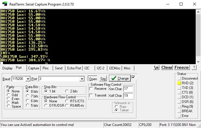
Time to compare these three sensors. I placed them on a single small breadboard so that they would be close to each other. For illumination I used a lamp that provides even light and is placed at a considerable distance from the board. This way the light is distributed evenly to each sensor. STM32 Studio will work perfectly for plots here. The light measurement on my desk with standard room lighting looks as follows.

The TEMT6000 phototransistor, after converting the value, indicates a much lower illumination level than the other sensors tested. Interestingly, the smartphone app shows about 575 lux, which is significantly higher than what all the sensors show. I covered all the sensors with my hand and, as expected, the readings dropped almost to zero and for each of the sensors, including the smartphone, the results are similar (about 10 lux).
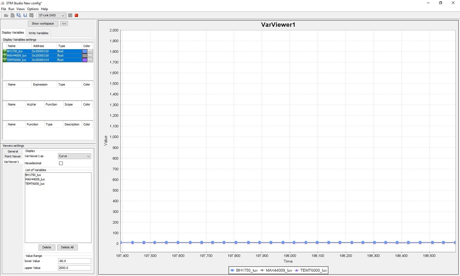
A surprise and a big disappointment comes with stronger illumination of all sensors.
As you can see, each one shows what it wants… The smartphone sensor shot up to about 2500 lux. Which value is closest to the truth? I can’t say without a professional, calibrated lux meter.
EDIT: After a deeper analysis
Alright, I spent a little more time with these sensors and the debug mode in Eclipse. I noticed that the ADC value for a strongly illuminated TEMT6000 is close to the maximum. If so, almost the entire supply voltage is dropping across the resistor. In reality it was about 3 V, because some drops across the collector-emitter junction of the phototransistor. Let’s calculate from Ohm’s law what current flowed through the factory 10 kΩ resistor.
I = 3 [V] / 10000 [Ω] = 0.0003 [A] = 300 [µA]
This implies that the maximum value in lux that the TEMT6000 can show with the factory 10 kΩ resistor is about 600 lux. I took a stronger lamp and indeed that’s the case. The measurement stops a bit before 700 lux. What now?
The resistor should be replaced. With what value? We basically have one constraint — the maximum collector current, which can be at most 20 mA, which equals about 40000 lux. Such a value is far too high for normal use. It will also reduce measurement resolution because the ADC can measure only 4096 levels. 10000 lux will be a better value. What resistor will be needed? 10000 lux is 5000 µA and to drop 3 V on the resistor at that current, it must have a value of:
R = 3 [V] / 0.005 [A] = 600 [Ω]
I don’t have such an SMD resistor on hand, but I do have 1 kΩ, which allows up to 6000 lux. And indeed the measurement works better, but the sensor still shows a much lower value than the other two — the digital ones. I wondered what else could influence this.
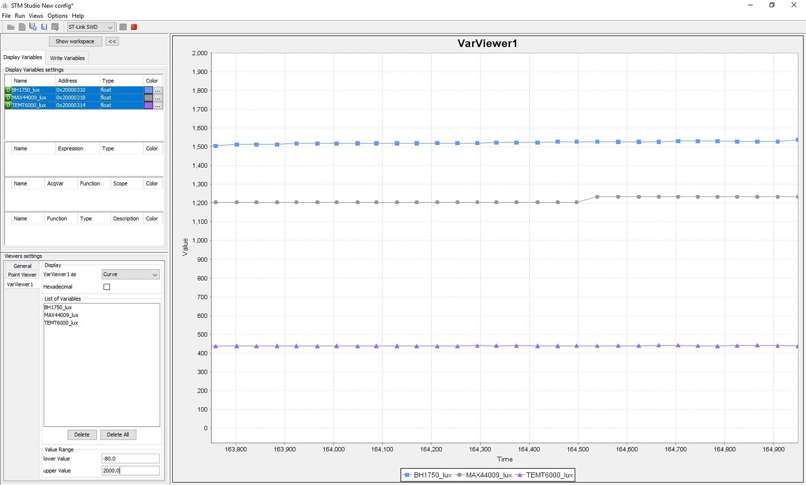
I checked the spectral response of these sensors. I took the graphs from each datasheet and put them on one chart. I also added the curve corresponding to how the human eye perceives light.
Unfortunately, measuring light is subjective. The rule in this type of measurement is that the sensor should have a response as close as possible to the human eye. As you can see, all my sensors today deviate somewhat from the ‘norm’. The TEMT6000 in general picks up a lot of light from the infrared range. I even checked the reaction of all three with a TV remote, and only the TEMT6000 reacted to the IR diode.
Unfortunately, I’m not good at photoelectronics and I won’t explain why the TEMT6000, despite being more sensitive over a wider range, gives much lower results. It would be great if someone could explain it in the comments. However, for accurate measurement of visible light I would cross out the TEMT6000. It may at most be suitable for dimming a display, and such an application is indeed listed in the datasheet.
Digital sensors have built-in circuits that process the signal falling on the photodiodes/phototransistors. There is probably some magic processing and compensation in them, hence the results are close to each other.
Summary
Light sensors that convert the amount of incident light into lux are very tempting devices. However, as direct comparisons have shown, although each responds to the amount of light as intended (the more light, the higher the indication), the absolute values vary. I would very much like to perform a comparison against a decent, certified lux meter. This would make it possible to determine which of the sensors tested today is worth buying. These sensors cost pennies, so I didn’t expect miracles from them. I wouldn’t use them to build a precise meter.
However, I wouldn’t completely write off each of them. As general-purpose sensors, when we want to check, for example, whether it is darker or brighter, they can work perfectly. It is not always necessary to know how many lux there are around. For example, the smartphone by default does not display the light intensity value anywhere. Its sensor only needs to determine whether it is bright or dark and, on that basis, set the backlight brightness. Such calibration can be performed for each sensor and as a result they can operate with roughly similar effect.
The project with code for all sensors is on my GitHub: link
If you noticed any mistake, disagree with something, would like to add something important or simply feel like discussing the topic, write a comment. Remember that the discussion should be polite and in accordance with the rules of the Polish language.
Podobne artykuły


0 Comments