Winter is approaching, so the media will once again be loud about the smog prevailing over Poland. Moreover, the authorities probably have no intention of moving away from coal, so we have to cope with pollution somehow. As a result, air quality sensors have become popular in recent years, and today I’ll be looking at one of them.
The most important parameters such a sensor should measure are PM10 and PM2.5 values. PM10 indicates the concentration of particles in the air with a diameter smaller than 10 µm. Likewise, PM2.5 refers to the amount of particles in the air with a diameter below 2.5 µm. These values may seem really small—and they are—because PM2.5 can penetrate the deepest parts of the lungs and thus enter the bloodstream. As usual, there are daily standards for such parameters. For PM10, three levels have been defined:
- Permissible – 50 µg/m³
- Information – 200 µg/m³
- Alarm – 300 µg/m³
For PM2.5, only a single permissible annual average limit of 25 µg/m³ is specified. Source.
Measurement
Professional measurement methods involve continuously drawing in a measured amount of air and feeding it through special filters that trap the appropriate particles. These filters are then weighed and, based on that, the dust concentration value is determined. This method is quite accurate, but it requires expensive equipment and effort.
There are less demanding methods on the market—laser-based measurement. They are less accurate but easy to implement. Such a solution works perfectly for everyday home use.
SDS011 Sensor
One of these inexpensive laser sensors is the SDS011 by Nova Fitness. It costs around 150 PLN in Poland. Compared to other electronics, it is relatively large at 71x70x26 mm. However, it includes everything needed for easy readout via an interface—fan, air channel, microcontroller, and of course a laser.
It requires a 5 V power supply, but Nucleo boards fortunately have such a pin. Current consumption in active state is quite high at 70 mA, which will have poor results for battery power. Fortunately, it has a sleep mode in which the power draw drops below 4 mA. This sensor measures both values of interest—PM10 and PM2.5—in the range 0÷999,9 µg/m³ with a maximum frequency of 1 measurement per second. The smallest particles it can detect are 0,3 µm and it measures with an accuracy of 15% but not worse than ±10 µm.
Unfortunately, the laser lifetime declared by the manufacturer is only 8000 hours of continuous operation. Luckily, the aforementioned sleep mode is available, so the lifetime can be significantly extended.
The SDS011 sensor can communicate with the outside world in two ways. The first and by far the most popular is UART. The second is PWM. I will check both.
More information can be found in the documentation
SDS011 Datasheet
.
Schematic and configuration
Since such sensors are often used to monitor outdoor conditions, there is a need to power them with batteries or a solar panel. Hence, a microcontroller with low power consumption is required. The STM32L053R8, which is included in one of the Nucleo kits, will work great here, and that’s what I used.
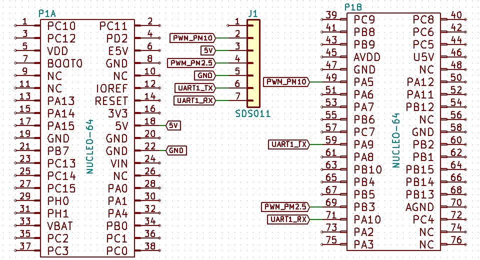

The sensor will be connected to UART1. I will use the second serial interface to print to the terminal. I set the pins for PWM readout as inputs of channels 1 and 2 of Timer 2. UART configuration for the sensor: 9600 8n1. Additionally, I enabled interrupts for UART1 and TIM2 and enabled them in the NVIC during HAL initialization.
UART
The UART communication protocol is described by the sensor manufacturer in the document:
SDS011 UART Protocol
. In the default mode, immediately after startup, the sensor will start sending a data frame with measurements every second. The simplest approach would be to just implement handling of this frame. But remember that the laser diode’s lifetime is limited to only 8000 hours. To extend this, we must use the UART commands that put the sensor to sleep and turn off the diode.
The data frame received from the sensor is always 10 bytes long. When the sensor settings are changed, it also sends a 10-byte confirmation. This makes parsing easier, but I chose not to parse command acknowledgments. I may add this later if it turns out that the sensor doesn’t behave as I’d like.
As for commands, in my opinion two are worth our time: putting the sensor to sleep (and, of course, waking it up) and setting the working period. While the sleep function is easy to imagine, what is this working period?
The sensor can enter sleep and wake up by itself without MCU intervention. You set the sleep duration in the range 0–30 minutes. Zero means standard operation with data sent every second. Setting another value tells the sensor to run for 30 seconds, send the measured data only once, and then go to sleep for the configured 1–30 minutes. Sounds great.
Why does it send data only once during those 30 seconds? I noticed that manually entering sleep and then starting the sensor introduces measurement errors. In the first moments, the sensor shows heavily underestimated values. The dust counting algorithm likely needs some time to self-calibrate. Therefore, in the mode with automatic pauses, the sensor runs for 30 seconds and only then sends the measurement result. Clever, isn’t it? If you want to sleep for longer, you must use the regular sleep, but remember about the underestimated readings for the first moments after waking up. Let’s move on to the functions.
In the header file, first uncomment the definition
#define SDS011_UART
The first function is, of course, initialization. It assigns a pointer to the UART, sets the sensor’s operating mode to continuous, and activates the interrupt after a complete frame is received from the device.
SDS011_SATUS Sds011_InitUart(UART_HandleTypeDef *huart);
The following functions are responsible for configuring the SDS011. Setting the working period, manually putting the sensor to sleep, and waking it up.
SDS011_SATUS Sds011_SetWorkingPeriod(uint8_t Period);
SDS011_SATUS Sds011_SetSleepMode(void);
SDS011_SATUS Sds011_WakeUp(void);
An important element is interrupt handling. After the entire frame arrives, the appropriate interrupt is triggered, in which the following function must be invoked:
void Sds011_UartRxCpltCallback(UART_HandleTypeDef *huart);
Paste it into the _weak function provided by HAL.
void HAL_UART_RxCpltCallback(UART_HandleTypeDef *huart)
{
#ifdef SDS011_UART
  Sds011_UartRxCpltCallback(huart);
#endif
}
What remains is reading the last value provided by the sensor. There are two functions for this.
SDS011_SATUS Sds011_GetPm2_5(uint16_t *Value);
SDS011_SATUS Sds011_GetPm10(uint16_t *Value);
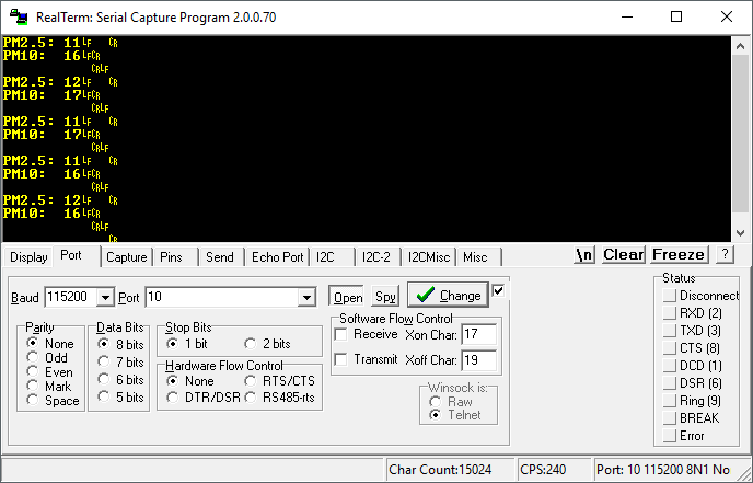
I printed the result to the terminal.
PWM
The second way to communicate with the sensor is PWM. Unfortunately, this is one-way communication and it is not possible to change the sensor’s operating mode. The only use case I see for such a solution is a place where continuous measurement is required and we don’t have a free UART. Nevertheless, I decided it would be great programming practice. The PWM period is as much as 1004 ms, i.e., about 1 Hz. Quite a slow signal for PWM measurements. On top of that, the STM32L053 can measure only one PWM at a time.
Therefore, I used the Input Capture mode on the second timer, measuring only the high-state duration. This mode reacts to a selected edge (or two), and at its occurrence, it latches the timer value at which it happened. I split the measurement into three stages.

The first point is the appearance of a rising edge on one of the signals—I chose PM10. At this moment, the timer is cleared, I change the interrupt reaction to the falling edge and start the interrupt again. At this point the counter is already ticking.
The second stop is the appearance of the first falling edge. You never know which falling edge will appear first. I don’t perform any calculations or reads here because the counter value is already safely latched in the appropriate register. I wait for the last edge.
The third point is the appearance of the second falling edge. At this moment, I restore the PM10 interrupt reaction to the rising edge, preparing for the next readout. Then I collect the values from the latched timer registers and start both interrupts again. Finally, I set the interrupt handling state variable back to the initial state.
The cycle repeats every second when new data arrives. You can analyze the interrupt code below:
void Sds011_TimerCaptureCallback(TIM_HandleTypeDef *htim)
{
	if(htim->Instance == htim_sds->Instance)
	{
		static uint8_t state = 0;
		if(state == 0) // Rising edge - begin
		{
			// Clear counter
			__HAL_TIM_SetCounter(htim_sds, 0);

			// Set edge to falling
			htim->Instance->CCER |= (1<<(Pm10_TimChannel_sds+1));
			HAL_TIM_IC_Start_IT(htim_sds, Pm10_TimChannel_sds);

			// Change state
			state = 1;
		}
		else if(state == 1) // First falling edge
		{
			// Change state only and wait for second edge
			state = 2;
		}
		else // Second falling edge
		{
			// Set edge back to Rising
			htim->Instance->CCER &= ~(1<<(Pm10_TimChannel_sds+1));

			// Get values
			Pm10 = __HAL_TIM_GetCompare(htim_sds, Pm10_TimChannel_sds) - 2;
			Pm2_5 = __HAL_TIM_GetCompare(htim_sds, Pm2_5_TimChannel_sds) - 2;

			// Enable Interrupts
			HAL_TIM_IC_Start_IT(htim_sds, Pm10_TimChannel_sds);
			HAL_TIM_IC_Start_IT(htim_sds, Pm2_5_TimChannel_sds);

			// Back to beginning - wait for next data
			state = 0;
		}
	}
}
You can use PWM mode by uncommenting in the header file
#define SDS011_PWM
Summary
The SDS011 air pollution sensor is a very interesting device. It can certainly be used in a home weather station to know whether to leave the house without exposing yourself to dust. I will definitely put the sensor outside my window.
I would personally treat PWM data reception as a curiosity. It’s much better to take advantage of the sensor’s sleep features provided by UART. One must remember that the laser used in the sensor is not long-lived.
Thank you for reading this post. If this topic appeals to you, let me know in the comments. I will also be grateful for topic suggestions you would like me to cover.
The code is, as usual, available on my GitHub: link
If you have noticed any errors, disagree with something, would like to add something important, or simply would like to discuss this topic, write a comment. Remember that the discussion should be polite and in accordance with the rules of the Polish language.
Podobne artykuły



0 Comments