I might be repeating myself, but ST’s kits are great. With every board we get a fully functional ST-Link programmer. Well, almost fully, but it covers 100% of the needs of the microcontroller mounted in the kits. Do you know all its functionalities? I could bet you don’t
, but I also assume advanced users are reading this, so I won’t risk it 😉
What is ST-Link
In short, it’s a programmer compatible with ST’s MCUs. ST-Link by default is an integral part of the Nucleo kits, but you can break it off and use it as a separate unit. Unfortunately, Nucleo-32 is an exception and we can’t physically separate the ST-Link from the main part. It’s similar with Discovery boards — you also won’t extract the programmer. Owning a few Nucleo boards, I have a stock of programmers for myself and my kids for life.

What can this little beast do? Many features are described in the documentation concerning programmers integrated with evaluation kits. Additionally, in the general documentation for Nucleco kits there’s a bit more. I recommend reading these documents.
TN1235 – Overview of the ST-LINK embedded in STM32 MCU Nucleo
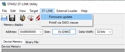
When approaching your unit for the first time, it’s worth updating the firmware in the programmer. You can do this using ST-Link Utility. You can download the latest version from ST’s website. Unfortunately, you need an account to download anything from them. The entire operation is very simple. Start the tool and connect a Nucleo or another board with an ST-Link. Then from the top menu select ST-Link >> Firmware Update.

After clicking Device Connect, the program should detect the programmer connected to the computer. Firmware Version is the current firmware that sits in the programmer. Below is the latest version that’s available. In my case, it’s the same as on the device. Clicking Yes starts the update procedure.
Programming
If you read the documentation carefully, you already know some features of the ST-Link. Its most important and basic function is undoubtedly programming the microcontroller. By connecting the Nucleo as a whole or other boards with an integrated ST-Link, we can upload our program to the MCU. You can do this via ST-Link Utility by pointing to the compiled binary with the firmware, or directly in the SW4STM32 environment, which is recommended by ST and which I use.
A cool “gimmick” is programming by dropping the binary onto the mass storage device under which the ST-Link mounts in the operating system. This method is dictated by the assumptions of the mbed project. Imagine you are in the field at a customer site, you don’t have your toolchain because your computer died, but someone sent you a binary with a bug fix. Thanks to the programmer mounting like a pendrive, you copy the binary onto it from a borrowed laptop or even from a phone with OTG support and… done. The chip is programmed. Great, isn’t it? I use this method very rarely, but I see potential in it.

I mentioned earlier breaking off the ST-Link from Nucleo boards. After such a procedure, we can program any chips by connecting through the CN4 connector. To make this possible, you also need to remove the jumpers from CN2. By removing these jumpers, you can also program external chips without breaking the ST-Link off the Nucleo. The CN4 connector has a standard pinout:
Note. Pin 1 is not used to power the programmed circuit! We connect this pin to the power supply of the programmed MCU so that the ST-Link can match it. Thanks to this, we can program chips at very low operating voltages. Even though the ST-Link note added to the Nucleo kits says it won’t work below 3 V — I successfully programmed and debugged chips powered at 1.8 V.
I always skip pin 6 😉
Debugging
Besides programming, we can truly debug the code. I remember how on AVR I always struggled with a debug LED that was set somewhere in the code as a trap. It had its charm and I still like to do it sometimes. The problem appears when, for example, the processor runs, communication looks correct, but still the program refuses to work properly. With a LED you won’t peek at variable values in RAM.
Likewise, you won’t stop the program at any point with a LED. But you can from the debugging level. You set so-called breakpoints that will stop the execution of the program when the MCU reaches them. It’s an incredibly powerful tool for solving problems, and problems are even 80% of writing code. Unless someone prefers the rubber duck method (link). I, of course, have my duck on the desk 😉
UART communication
ST-Link is simultaneously a UART <=> USB converter. It creates a virtual COM port in our computer’s operating system. Thanks to this, we can print whatever we want to the terminal on our PC. Not only print, because we can also receive from the PC. Great stuff. For this purpose, UART2 located on pins PA2 and PA3 is used.
Just like programming, using the UART <=> USB conversion is possible outside the evaluation boards. This is possible via the CN3 connector, to which we feed the microcontroller’s UART. However, there isn’t a convenient jumper to disconnect it like in the case of programming. To use UART externally without breaking the ST-Link off, you need to desolder jumpers SB13 and SB14 located on the bottom of the PCB.
Semihosting
You probably haven’t heard of this. I myself learned about it quite recently. What if you wanted to print something to the computer, but you don’t have any free UART or USB interface because everything is occupied by peripherals in the device? No chance, right? And yet! The so-called semihosting comes to the rescue. It’s a feature that prints to gdb, so you only use it in debug mode. Unfortunately, it only works one way, but during debugging that’s mainly the direction we use — we send to the PC. Another drawback is the significant slowdown of the MCU’s program execution, so you have to disable this method in the target microcontroller program. Failing to start the MCU in debug mode will also prevent proper operation if semihosting is used. How to configure it and how to use it? Let’s do it!
You need a special assembly function in the code that writes to the ST-Link interface.
void send_command(int command, void *message) {
	#ifdef DEBUG
	__asm("mov r0, %[cmd];"
	"mov r1, %[msg];"
	"bkpt #0xAB"
		:
		: [cmd] "r" (command), [msg] "r" (message)
		: "r0", "r1", "memory");
	#endif
}
As you can see, I wrapped this function in an #ifdef. Thanks to this, I can quickly disable semihosting if I don’t want to use it. There’s also all the surrounding code in the form of printing functions.
#define INT_DIGITS 19 /* enough for 64 bit integer */

char *itoa(int i)
{
	static char buf[INT_DIGITS + 2];
	char *p = buf + INT_DIGITS + 1; /* '\0' */
	if (i >= 0) {
		do
		{
			*--p = '0' + (i % 10);
			i /= 10;
		} while (i != 0);
		return p;
	}
	else { /* i < 0 */
		do
		{
			*--p = '0' - (i % 10);
			i /= 10;
		} while (i != 0);
		*--p = '-';
	}
	return p;
}

void prints( const char* str )
{

	uint32_t len = strlen(str);
	uint32_t i = 0;

	for( i = 0; i < len; i+=4)
	{

		uint32_t buflen = 4;
		if( i+4 >= len ) buflen = len-i;
		size_t m[] = { 2/*stderr*/, (size_t)str, buflen/sizeof(char) };
		send_command(0x05/* some interrupt ID */, m);
		str+=4;
	}
}

void printc( char c )
{
	char buf[2];

	buf[0] = c;
	buf[1] = 0;

	prints(buf);
}

void printi( int32_t i )
{
	prints( itoa(i) );
}

char *convert(unsigned int num, int base)
{
static char Representation[]= "0123456789ABCDEF";
	static char buffer[50];
	char *ptr;

	ptr = &buffer[49];
	*ptr = '\0';

	do
	{
		*--ptr = Representation[num%base];
		num /= base;
	}while(num != 0);

	return(ptr);
}

void print(char* format, ...)
{

	char *traverse;
	unsigned int i;
	char *s;
	double d;

	va_list arg;

	va_start(arg, format);

	/// Pack buf per 4 characters (last is always NULL)
	char buf[5];
	memset(buf, 0, 5);
	int t = 0;

	for(traverse = format; *traverse != '\0'; traverse++)
	{
		if (*traverse != '%')
		{
			if( t == 5 )
			{
				prints(buf);
				memset(buf, 0, 5);
				t = 0;
			}

			buf[t%5] = *traverse;
			t++;
			continue;
		}

		prints(buf);
		memset(buf, 0, 5);
		t = 0;

		traverse++;

		/// Module 2: Fetching and executing arguments
		switch(*traverse)
		{
			/// Fetch char argument
			case 'c' : i = va_arg(arg,int);
				printc(i);
				break;

			/// Fetch Decimal/Integer argument
			case 'd' : i = va_arg(arg,int);
				if(i<0)
				{
					i = -i;
					printc('-');
				}
				prints(convert(i,10));
				break;

			/// Fetch floating point argument
			case 'f' : d = va_arg(arg, double);
				if(d<0)
				{
					d = -d;
					prints("-");
				}
				i = (unsigned int)d;
				prints(convert(i, 10));
				printc('.');

				d = d - i;
				if (d*10.0 < 1.0)
					printc('0');
				if (d*100.0 < 1.0)
					printc('0');

				/// Round to 3 decimal places
				prints(convert((int)round(d*1000.0), 10));
				break;

			/// Fetch Octal representation
			case 'o': i = va_arg(arg,unsigned int);
				prints(convert(i,8));
				break;

			/// Fetch string
			case 's': s = va_arg(arg,char *);
				prints(s);
				break;

			/// Fetch Hexadecimal representation
			case 'x': i = va_arg(arg,unsigned int);
				prints(convert(i,16));
				break;
		}
	}

	prints(buf);
	memset(buf, 0, 5);

	va_end(arg);
}

[/cc]
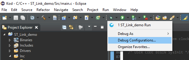
When we already have the code ready, we need to configure SW4STM32 to receive messages in gdb. Open the debug profile configurations.
In the Startup tab of the
monitor arm semihosting enable
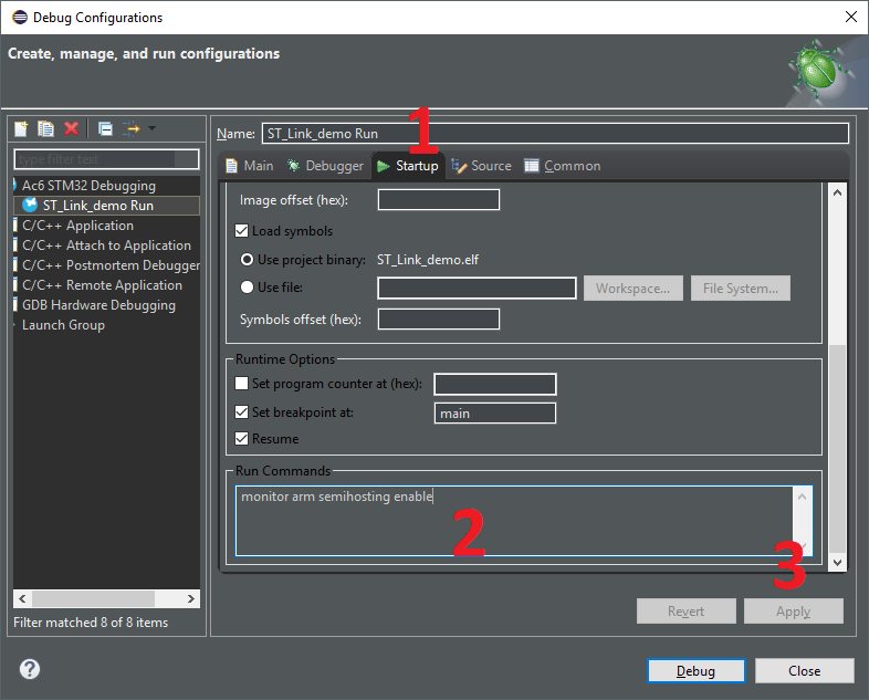
in the
Remember to comment out the code for semihosting if you’re not using it. You can do this, for example, with a simple #define as I mentioned above.
After completing these steps, we can print in the code, e.g., for testing in the main program loop between sending a message over UART and the cyclic LED blink:
while (1)
{
/* USER CODE END WHILE */

/* USER CODE BEGIN 3 */
  uint8_t message[] = "UART over ST-Link \n\r";
  HAL_UART_Transmit(&huart2, message, sizeof(message)-1, 100);

  print("Semihosting test \n");
  HAL_GPIO_TogglePin(LED_GPIO_Port, LED_Pin);
  HAL_Delay(500);
}

/* USER CODE END 3 */
Running the program in debug mode generates cyclic prints of the test message to the gdb console.
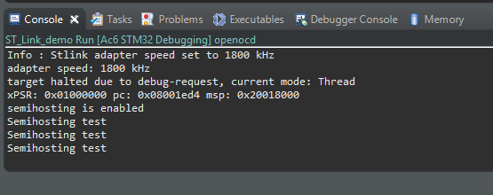
Admit it, this is great. You don’t need a free UART for simple debugging — ST-Link, which you always have, is enough!
If you liked this post, like it or share it further. I’ll be very grateful for any activity.
As usual, the source code used in the post can be found on GitHub: link
If you noticed any error, disagree with something, or simply think you’d like to discuss this topic, write a comment. Remember that the discussion should be polite and in accordance with the rules of the Polish language.
Podobne artykuły


0 Comments