In the last >>part<< I examined the refresh time of a 16×2 LCD on STM32 using a 4-bit communication bus and a predetermined wait time for processing the supplied data. Today I will check how reading
the so-called busy flag by the MCU will affect the refresh time. Let’s go!
4-bit bus with busy flag checking
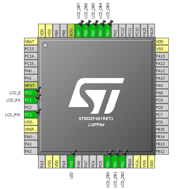
To read the busy flag from the display controller, I need to modify the wiring and the code. The modifications I made are:
-
- Pin no. 5, i.e., RW, will this time be connected to the STM32, which will control the direction of data flow on the bus. Thanks to this, it will be possible to read data from the LCD.
- Changing the direction of the GPIO dedicated to communication with the display “on the fly”. The library is supposed to do this by itself.
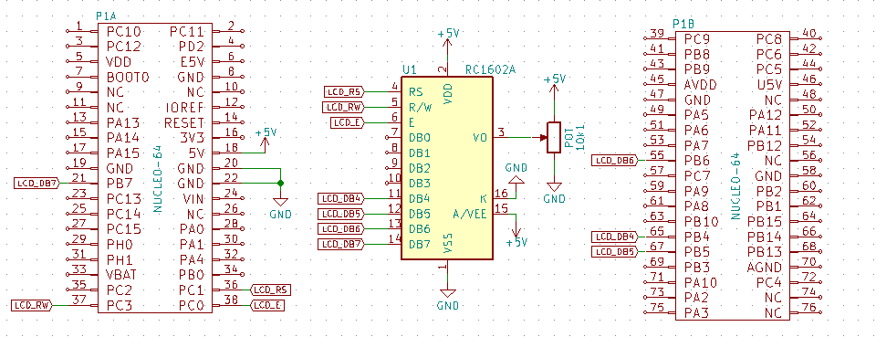
I will configure the GPIO for pins LCD_DB4…LCD_DB7 as Input or Output in the way suggested by STM32CubeMX. I have also appropriately modified the transmit and receive functions.
As a base I will use Nucleo F401RE.


static void LCD_DataOut()
{
	GPIO_InitTypeDef GPIO_InitStruct;

	GPIO_InitStruct.Pin = LCD_DB4_Pin|LCD_DB5_Pin|LCD_DB6_Pin|LCD_DB7_Pin;
	GPIO_InitStruct.Mode = GPIO_MODE_OUTPUT_PP;
	GPIO_InitStruct.Pull = GPIO_NOPULL;
	GPIO_InitStruct.Speed = GPIO_SPEED_FREQ_LOW;
	HAL_GPIO_Init(GPIOB, &GPIO_InitStruct);
}

static void LCD_DataIn()
{
	GPIO_InitTypeDef GPIO_InitStruct;

	GPIO_InitStruct.Pin = LCD_DB4_Pin|LCD_DB5_Pin|LCD_DB6_Pin|LCD_DB7_Pin;
	GPIO_InitStruct.Mode = GPIO_MODE_INPUT;
	GPIO_InitStruct.Pull = GPIO_NOPULL;
	HAL_GPIO_Init(GPIOB, &GPIO_InitStruct);
}

//
// Write byte to LCD
//
uint8_t LCD_ReadByte(void)
{
	uint8_t result = 0;
	LCD_DataIn();

	SET_LCD_RW;

	SET_LCD_E;
	result = (LCD_GetDataPort() << 4);
	RESET_LCD_E;

	SET_LCD_E;
	result |= LCD_GetDataPort();
	RESET_LCD_E;

	return result;
}

//
// Check Busy Flag
//
uint8_t LCD_CheckBusyFlag()
{
	RESET_LCD_RS;
	return LCD_ReadByte();
}

//
// Write byte to LCD
//
void LCD_WriteByte(uint8_t data)
{
	LCD_DataOut();

	RESET_LCD_RW;

	SET_LCD_E;
	LCD_SetDataPort(data >> 4);
	RESET_LCD_E;

	SET_LCD_E;
	LCD_SetDataPort(data);
	RESET_LCD_E;

	// HAL_Delay(1);
	// Delay_us(120); // Wait for data processing
	while((LCD_CheckBusyFlag() & (1<<7))); // Wait for data processing
}
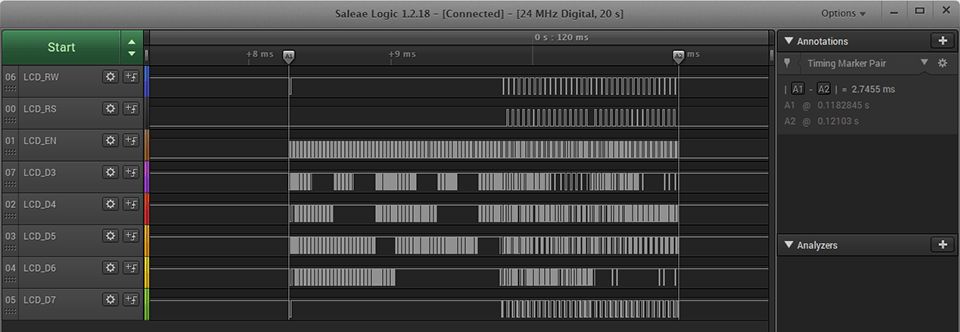
I run the code and… WOW! Although the microcontroller performs a ton of operations on the pins, the frame refresh time was only 2,74 ms! Is this speed worth one GPIO pin? I think in many cases definitely yes.

Or maybe I can shave off a bit more? The LCD controller offers up to an 8-bit communication bus width. I will check whether doubling the amount of data sent at once will halve the frame refresh time. First I will check without reading the busy flag.
8-bit bus without busy flag checking
Due to the hopelessly long refresh time I achieved using only the delay functions built into STM32HAL, I will skip considering this method for 8-bit. I will perform measurements only using a function operating on a timer.
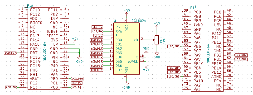
I start by connecting the remaining 4 lines, i.e., LCD_DB0…LCD_DB3.
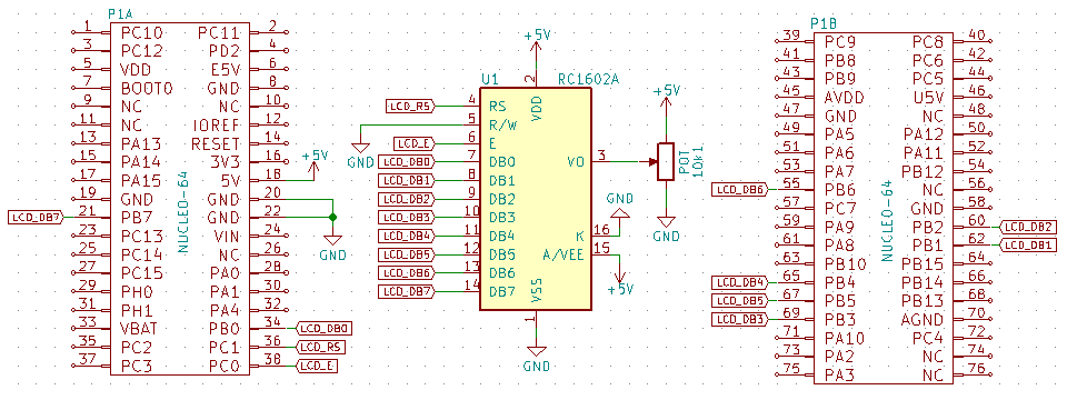
The code modification consists of assigning new functions to the appropriate pins in STM32CubeMX

…and modifying the code for the wider bus. The functions related to setting the GPIO pins, sending one byte of data, and the display initialization function change, which now sets the LCD controller to 8-bit mode.
The time obtained is nothing special. Basically, almost nothing got shorter compared to the 4-bit version. The whole frame transferred in 7,11 ms.

8-bit bus with busy flag checking
For the 4-bit mode, replacing delays with reading LCD busyness worked brilliantly – the time decreased significantly. I will check whether for 8-bit the result will be equally spectacular.
I rework the code and… to be honest, I expected something better 🙁 In this way I got 2,74 ms, i.e., exactly the same result as with the 4-bit mode.
Further optimization?
You can still replace the HAL functions for controlling GPIO with direct register operations. Is it worth going further down this road? Probably not. It should be possible to shave off maybe 0,2 ms, because the time to set GPIO unfortunately has a negligible effect – the waiting time for the LCD controller is definitely greater, and I won’t shorten that.
Looking at the waveforms you can also infer quite an interesting thing. Namely, the first 1,5 ms at the beginning of the transfer is spent clearing the display. With busy-flag handling, this is more than half the time needed to display two full lines! Maybe that’s where to try to bite? For example, instead of sending the clear command, write spaces, hmm? Or send a pre-prepared complete buffer from the microcontroller’s RAM? There are many ways to buffer and in the future a thread on this topic will certainly appear on the blog.
Summary
I’ve reached the end 🙂 I examined all 4 possible ways of communicating with a popular LCD display with a controller compatible with HD44780 using the STM32F401RE microcontroller. The research results are presented in the table below.
| Mode | Time |
|---|---|
| 4-bit HAL_Delay | 67,29 ms |
| 4-bit without BF | 7,14 ms |
| 4-bit with BF | 2,74 ms |
| 8-bit without BF | 7,11 ms |
| 8-bit with BF | 2,74 ms |
Which mode to use? You can immediately reject the method using the built-in HAL_Delay. This time is definitely unacceptable! Don’t waste your life, I don’t recommend it.
Comparing the two 4-bit modes shows how big an impact reading the busy flag has. You don’t have to guess when the controller is ready to accept data, lengthening the whole procedure. Reducing the time by more than 2.5x costs only one GPIO pin. This time can be very valuable in a more complex project.
And what about 8 bits? Smoke and mirrors. The results are almost identical to those with a data bus that’s twice as narrow. What does this mean? You can completely skip this mode when using alphanumeric displays. Entering 8-bit mode is a waste of four valuable microcontroller pins.
If you like the display, you can buy it in various variants in my store.
The test code along with the library can be found on my GitHUB: link
In the end, I encourage you to discuss in the comments the handling of the LCD display on STM32. Do you think I made a mistake somewhere? Do you have an interesting idea on what can be improved? Share it in the comments! Remember that the discussion should be polite and in accordance with the rules of the Polish language.
Podobne artykuły


0 Comments