I often come across the statement that it’s better to connect an LCD display via an I²C expander because it “eats” only two microcontroller pins instead of a minimum of 6. It’s true that it saves pins, but as we all know—nothing comes for free. Today I’ll check for you what you need to account for when you connect an LCD over I²C using popular modules based on PCF8574 chips.
Previous posts about the 16×2 LCD can be found here:
16×2 LCD on STM32 + HAL part 1
16×2 LCD on STM32 + HAL part 2
LCD to I²C converter
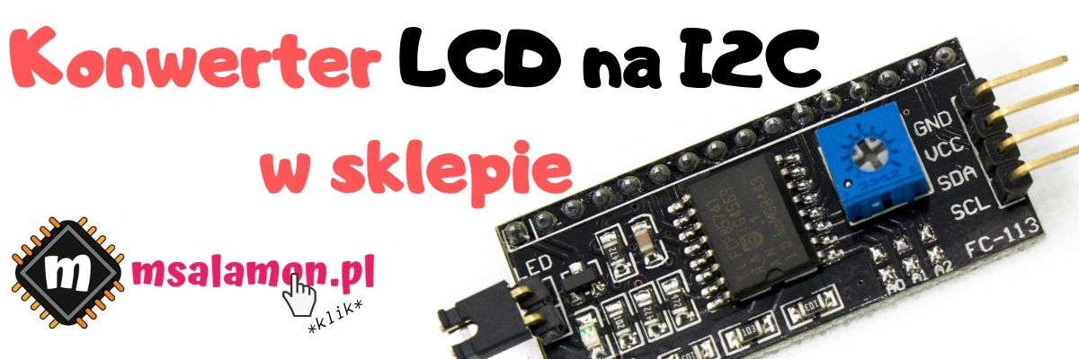
The LCD to I2C converter is very simple in construction. It includes the aforementioned PCF8574 expander, a few resistors, a contrast adjustment potentiometer, and a transistor. Let’s take a look at the datasheet of the IC.
The first thing that stands out is that the available ports are bidirectional, meaning we can both write to outputs and read from them. That’s good, because it gives us the option to work with the display’s busy flag.
Powering the PCF8574
The PCF8574 can be powered from as low as 2.5 V, which is also good news, but unfortunately the display needs 5 V for the contrast divider and for the backlight. While a dimmer backlight might be tolerable, with 3.3 V applied to the contrast there’s practically no chance for the display to work correctly. The only rescue would be an LCD with a fixed contrast. They are less popular and harder to get. So it turns out the entire converter circuit should be powered from 5 V. OK, but what about the communication pins? After all, the STM32 runs at 3.3 V! Nothing to worry about, because almost all I/O pins of the STM are 5V-tolerant. All right, but in the other direction? Will the expander recognize a high level on the I²C lines? The high level on the PCF8574 is interpreted from 0.7 * VDD, which at 5 V supply is 3.5 V. Ouch—0.2 V above what the STM32 can provide…
There are two solutions (actually 3 on deeper thought). First, you can use a level shifter and be sure the IC will always read what was sent to it. A good solution, but it introduces more components.
The second solution is simply to try with what you have 🙂 From my experience, chips interpret a high level at a slightly lower voltage than the datasheet states. Just a safety margin. Unfortunately, this can vary across IC batches, and for example, you can get a series that strictly adheres to the documented parameters. I don’t recommend this when building a final device, e.g. for sale. It’s better then to stick to what the manufacturer states on paper. It will help you avoid surprises that are your fault. It’s different for a desk test or hobby/amateur devices 🙂 You can turn a blind eye once, and that’s what I’m doing now.
And that’s 100% true for push-pull outputs. Now recall what the outputs for the I²C interface look like. We’re dealing with open-drain outputs. In short—we have only one active state—logical zero. The one is set by the pull-up resistor on the SDA and SCL lines. As you can see in the converter schematic, these resistors are connected to VDD, i.e. 5 V. Hence the high level on the communication lines will be at that level, regardless of the operating voltages of the communicating devices. It’s important that the outputs of these devices tolerate such a high voltage for a logical one. Both the PCF8574 and the STM32 tolerate 5 V on their inputs. It will work 🙂
I²C communication speed
There’s one parameter that doesn’t put a smile on my face. It’s the maximum I²C clock frequency. Unfortunately, the chip only supports Standard Mode, i.e. 100 kHz. You can try to overclock the bus, but there’s no guarantee it will work correctly. This will have a huge impact on the results of my observations.
Converter schematic
I found a schematic of such a Chinese converter on the Internet.
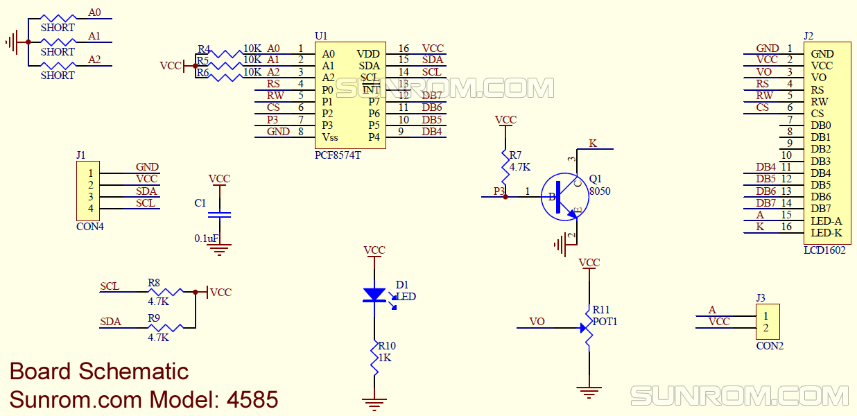
What interesting things can we read from it? The R/W pin control is available. So you can read the busy flag, which significantly speeds up communication in classic control.
Another curiosity is the backlight connected through a transistor and controlled by the expander’s P3 port. So you can control the backlight, but I wouldn’t count on PWM. Just simple on-off.
There are address jumpers, so if you insist you can connect 8 displays to a single I²C bus.
The expander is connected in the LCD’s 4-bit mode. That’s not a problem because I’ve already shown that 8-bit operation makes no sense.
STM32CubeMX schematic and configuration
To compare I²C communication with classic display control, I’ll need conditions as similar as possible. That’s why I’ll use the Nucleo with STM32F401RE, just like in the posts where I compared classic methods of controlling the HD44780 controller. Set the HCLK clock to 84 MHz. Connect the expander to I2C1 according to the schematic below.
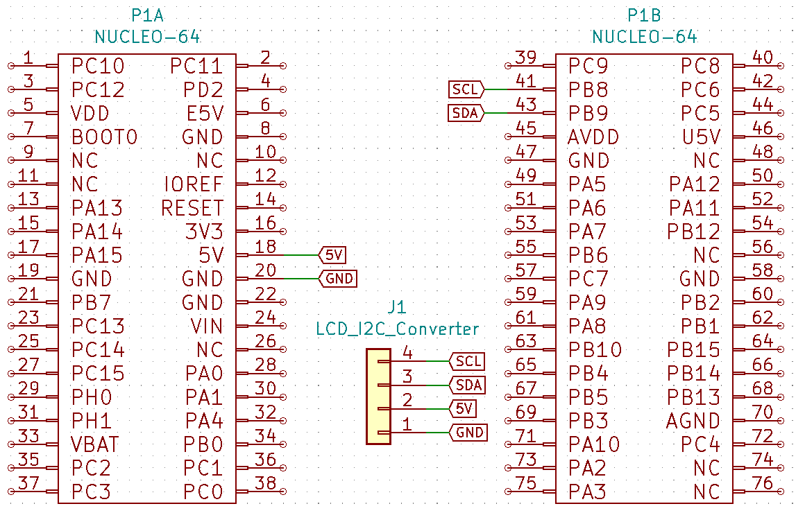
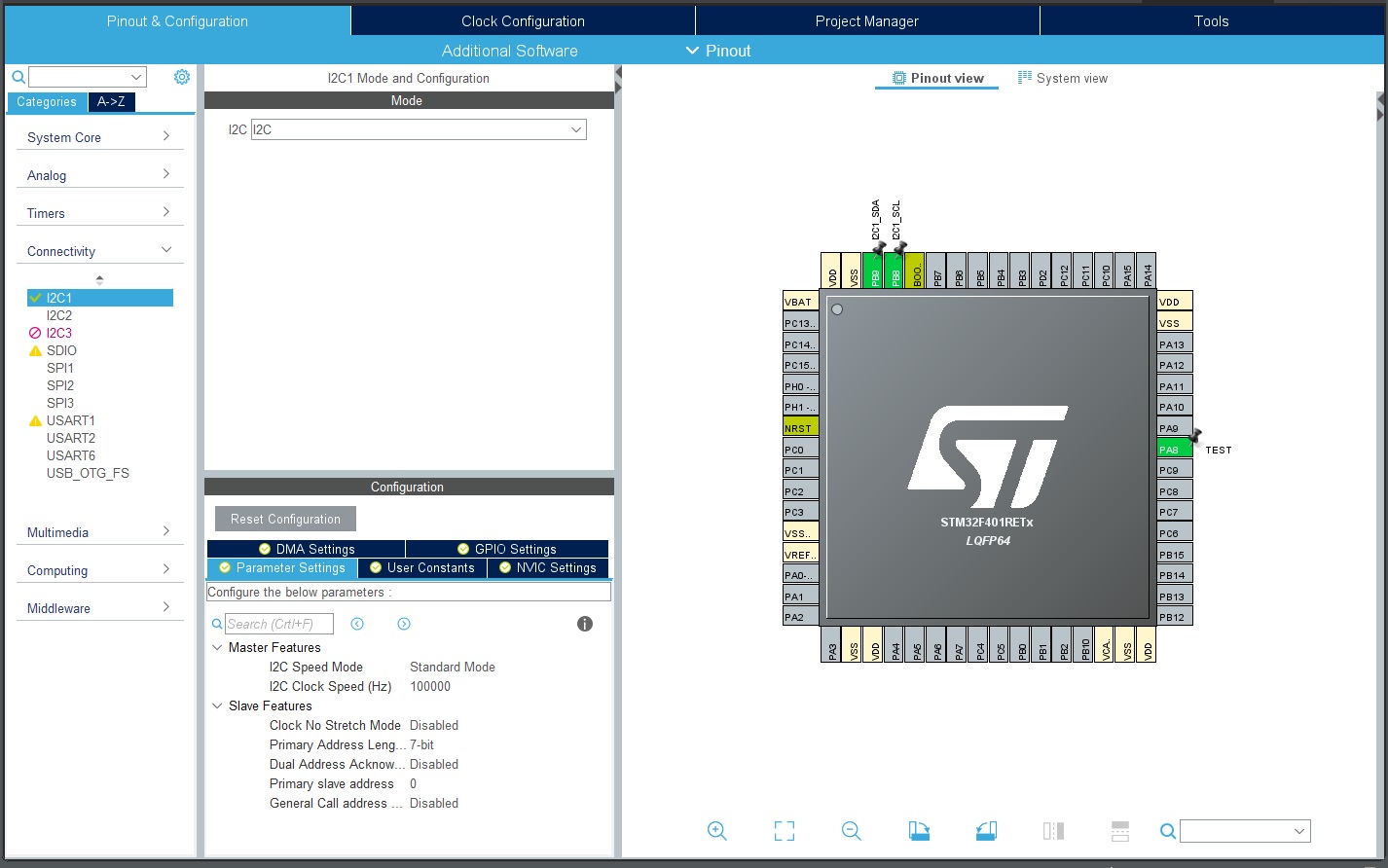
As the IDE I’ll use STM32CubeIDE, where I can configure the project right away. You need to set two things. First, I2C1 on pins PB8 and PB9 (by default it will be PB6 and PB7). Speed Mode as Standard Mode and 100 kHz clock. Leave the rest as default.
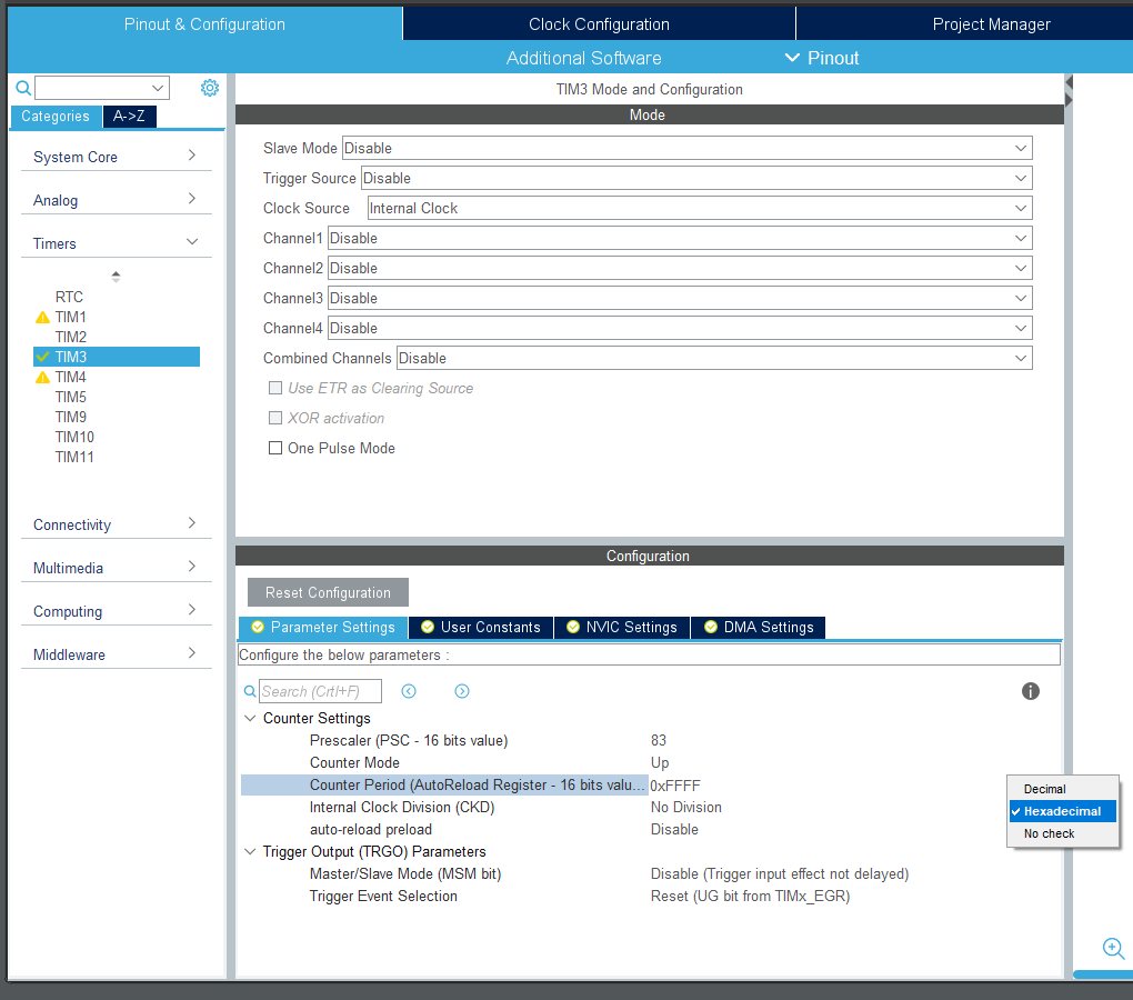
The second thing you need to set is a timer. You might very well ask why. If you remember the previous LCD posts, there was a delay used with a 1 µs resolution. Unfortunately, HAL doesn’t provide a timer with such a small tick, so you have to create one yourself. Choose TIM3, select Internal Clock as the clock source. Enter 83 in the Prescaler field (this will bring the clock down to 1 MHz, which gives exactly 1 µs per tick) and set the maximum counter value to 0xFFFF (on the right side of the value field you can choose hexadecimal formatting).
Generate the project with peripheral files separated.
Code for the I2C converter
Most of the code I use for handling the LCD is already ready. I’ll use what I wrote for the classic interfaces. The library is written so that the only thing I have to change is the functions that send data to the display and read from it.
For convenience I created an 8-bit variable to hold the byte I send to the expander. Thanks to it I also have an overview of what was previously sent. Therefore, I won’t have to wonder what state the control pins were previously in. I’ll make all changes bitwise using masking.
Because the control bits are also connected to the expander, I had to add functions that modify those pins on the converter. The function for setting data is similar to the classic version. Only at the end do you have to send the set data over I²C.
//
// Send/Read data to/from expander function
//
void LCD_SendDataToExpander(uint8_t *Data)
{
	HAL_I2C_Master_Transmit(hi2c_lcd, LCD_I2C_ADDRESS, Data, 1, LCD_I2C_TIMEOUT);
}

//
// Set data port
//
static inline void LCD_SetDataPort(uint8_t Data)
{
	ByteToExpander &= ~(0xF0); // Clear Data bits

	if(Data & (1<<0))
	ByteToExpander |= D4_BIT_MASK;

	if(Data & (1<<1))
	ByteToExpander |= D5_BIT_MASK;

	if(Data & (1<<2))
	ByteToExpander |= D6_BIT_MASK;

	if(Data & (1<<3))
	ByteToExpander |= D7_BIT_MASK;

	LCD_SendDataToExpander(&ByteToExpander);
}
//
// Control signals
//
static inline void LCD_SetRS(void)
{
	ByteToExpander |= RS_BIT_MASK;
	LCD_SendDataToExpander(&ByteToExpander);
}

static inline void LCD_ClearRS(void)
{
	ByteToExpander &= ~(RS_BIT_MASK);
	LCD_SendDataToExpander(&ByteToExpander);
}

static inline void LCD_SetEN(void)
{
	ByteToExpander |= EN_BIT_MASK;
	LCD_SendDataToExpander(&ByteToExpander);
}

static inline void LCD_ClearEN(void)
{
	ByteToExpander &= ~(EN_BIT_MASK);
	LCD_SendDataToExpander(&ByteToExpander);
}

static inline void LCD_SetRW(void)
{
	ByteToExpander |= RW_BIT_MASK;
	LCD_SendDataToExpander(&ByteToExpander);
}

static inline void LCD_ClearRW(void)
{
	ByteToExpander &= ~(RW_BIT_MASK);
	LCD_SendDataToExpander(&ByteToExpander);
}

void LCD_BacklightOff(void)
{
	ByteToExpander &= ~(BL_BIT_MASK);
	LCD_SendDataToExpander(&ByteToExpander);
}

void LCD_BacklightOn(void)
{
	ByteToExpander |= BL_BIT_MASK;
	LCD_SendDataToExpander(&ByteToExpander);
}
The rest remained almost unchanged, but more on that in a moment.
As you remember, I had a special function for testing communication times. It cleared the LCD and wrote all the characters to the display.
while (1)
{
	HAL_GPIO_WritePin(TEST_GPIO_Port, TEST_Pin, 1);
	// Measurement start
	LCD_Cls();
	LCD_Locate(0,0);
	LCD_String(" STM32 + HD44780");
	LCD_Locate(0,1);
	LCD_String("www.msalamon.pl ");
	// Measurement end
	HAL_GPIO_WritePin(TEST_GPIO_Port, TEST_Pin, 0);
	HAL_Delay(500);
}
As a reminder, I’m posting the table with the previous results for 4- and 8-bit modes, with and without the busy flag.
| Mode | Time |
|---|---|
| 4-bit HAL_Delay | 67,29 ms |
| 4-bit without BF | 7,14 ms |
| 4-bit with BF | 2,74 ms |
| 8-bit without BF | 7,11 ms |
| 8-bit with BF | 2,74 ms |
Let’s see if the test result will be similar. First up is handling without reading the busy flag. Delay implemented by a timer with a 1 µs tick. As I’ve shown before, there’s no point in using the HAL delay.

Unfortunately, a time CATASTROPHE. As much as 55,72 ms. The same operation in 4-bit mode without the busy flag took 7,14 ms, which means the expander is 7.8 times slower. Those 55 ms are already so long that you can observe flicker on the second row during refresh.
OK, but what about the busy flag? In earlier considerations it helped significantly. Well, I wrote busy-flag handling, but unfortunately it’s pointless with the expander. Why? To get this flag you have to read data from the display. Each time you want to read from the PCF8574, you need to configure it accordingly (there are no registers). For a whole byte, you need to perform two such reads (4-bit mode). This means the time needed to read one byte from the LCD is ~1.79 ms.

Meanwhile, the wait for the display to process the data is at most about 100 µs. In that case, there’s no point reading the busy flag, because by the time you retrieve it over I²C, it will have been set ages earlier. A similar situation occurs with command processing by the HD44780 controller. The maximum processing time is about 1.5 ms. Still less than reading one byte through the expander. Therefore, the procedure of reading the busy flag through the expander is a complete waste of time…
That’s why I decided to remove the functions responsible for reading from the display over I²C entirely. There’s no point tempting fate and throwing the less experienced into potential trouble.
If the chip supported higher I²C clock speeds, the result would be much better. Unfortunately, since it’s an old chip, there’s nothing to hope for. You would need to use newer and more efficient expanders. If there’s interest, I’ll test the LCD with, for example, the MCP23017 or a similar one.
Summary
It’s worth saying something about what came out of my test.
| Mode | Time |
|---|---|
| 4-bit HAL_Delay | 67,29 ms |
| 4-bit without BF | 7,14 ms |
| 4-bit with BF | 2,74 ms |
| 8-bit without BF | 7,11 ms |
| 8-bit with BF | 2,74 ms |
| I2C expander | 55,72 ms |
The I2C expander reduces the number of MCU pins needed, and that is an undeniable advantage. You must remember, however, that you pay for fewer pins with communication time to the display. An almost 8x slowdown may not be insignificant.
My library is not perfect and you must remember that it works in a blocking fashion. That’s why it’s important that these blocking times are as short as possible, and classic LCD connection ensures that.
The very fact that a clear display flicker is visible can be a major drawback. So when is it worth using such a converter?
In my opinion, in situations when you build a device with a very rarely refreshed display. Then such a connection makes sense. The data being displayed is not very dynamic and there’s no need to constantly monitor it. These can often be low-power devices that have few pins available.
And what’s your opinion about this type of expander? Share it in the comments.
You can find the full project along with the library on my GitHub as usual: link
If you noticed any mistake, disagree with something, would like to add something important, or simply feel like discussing the topic, write a comment. Remember that the discussion should be polite and in accordance with the rules of the Polish language.
Podobne artykuły






0 Comments