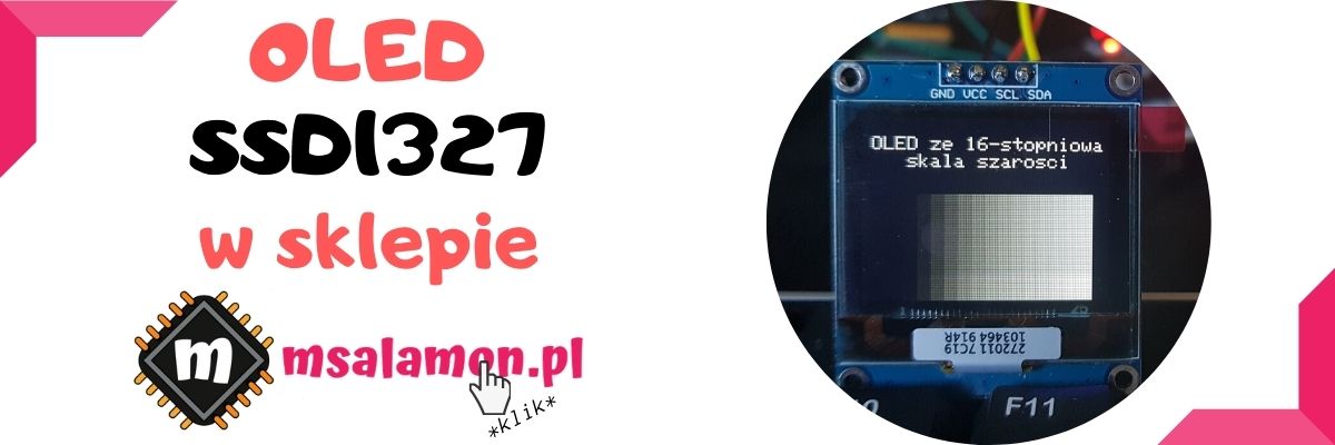
Recently I did a bit of theorizing about an OLED with a 16-level grayscale. We already know how those 16 colors are obtained and how the display’s RAM memory is organized. Time to display something on it, right? First, we’ll try using a graphics library from a regular monochrome OLED, which I used for the SSD1306. Let’s get to it!
The wiring is so simple that I won’t draw it. I connected to I²C1 with pins remapped to those on the Arduino connector.
For now I left I²C1 in the default 100 kHz configuration. Later there will be time for changes and comparisons.
Initializing the SSD1327 OLED
At first I wanted to write the initialization procedure myself. After all, it’s just a few registers and with the documentation you can achieve a satisfactory result sooner or later. Well, yes… later. I thought about it for a while and realized that the controller is connected to the pixels in a rather non-obvious way. The first thing I ran into was the image being displayed upside down by default, but that was fairly easy to fix.
Only later did I notice that the pixels are slightly shifted… I fought with it for a good 10 minutes, until I decided to give up. I started searching the Internet for some ready-made code from which I could pull the initialization procedure.
Remember that there’s nothing wrong with using ready-made solutions, as long as we know what they do and what they can be used for. Often there’s no point reinventing the wheel. That’s usually why manufacturers provide demo code—to be used. Well, yes—manufacturers. Unfortunately, with an OLED fromNo Name companies, we may not find the manufacturer’s code. So you have to rely on, for example, Arduino libraries.
How surprised I was when I saw that this OLED isn’t particularly popular among Arduino folks! Luckily, the u8g2 library has the initialization for these OLEDs built in. Admittedly it’s written a bit cryptically, but I managed to decipher it into human language. So I took the lib, copied it and… it worked. Thanks, Arduino friends, for the help! 🙂
By the way, someday I’d try to run this library on an STM32 under HAL. What do you think? Let me know in the comments!
The commands of the SSD1327 controller itself are very similar to those from the SSD1306, so I kept the convention of writing the library. Thanks to that, a lot of work was saved. This is what the initialization looks like.
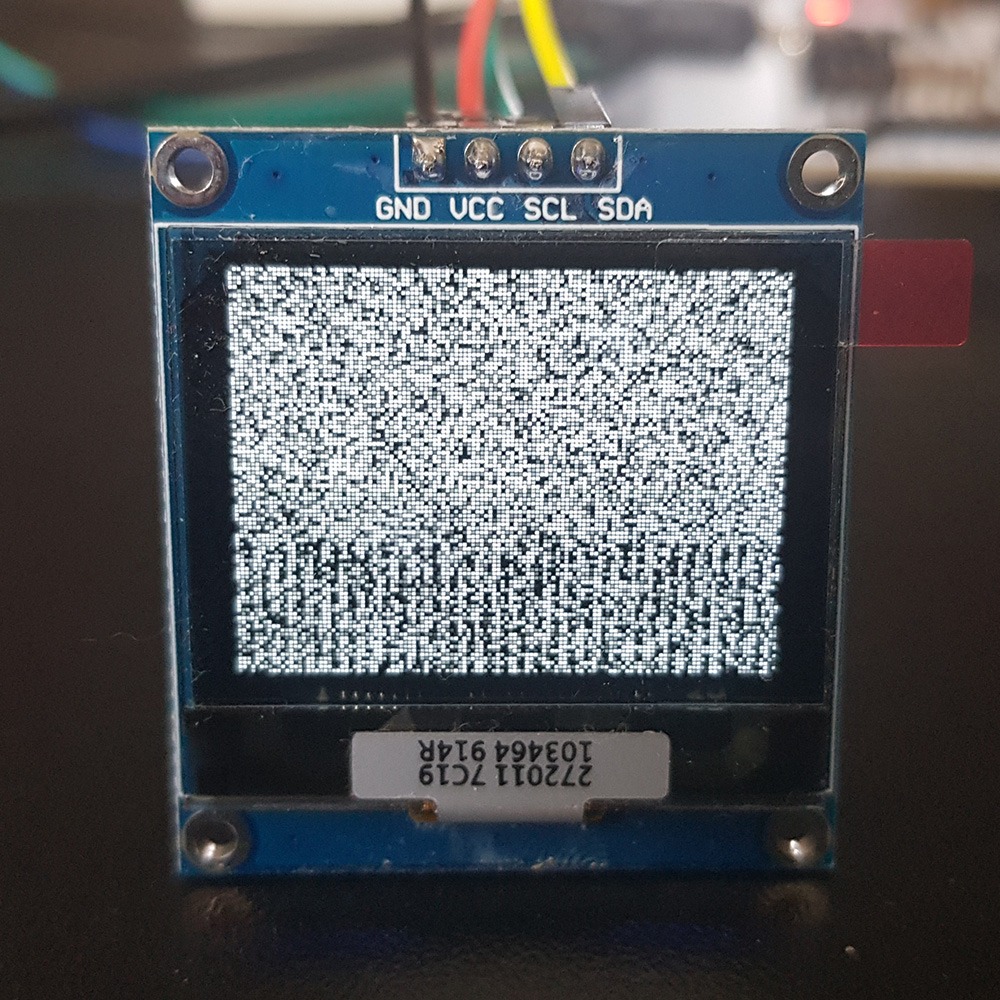
After running this code, what appears on the display is… a galaxy!
If you still don’t know where it comes from, I’ll explain. RAM has the property that after applying power, all cells settle into “random” values. Since the RAM reflects what is visible on the display, we get such an image. So it’s enough to clear this RAM for it to be uniform—e.g. turn off all pixels.
Buffering, setting a pixel, and transfer to the display RAM
In the previous post I pointed out a small problem with setting the color of a single pixel in this display. It’s that one RAM byte holds information about two adjacent pixels. So a good solution will be buffering such an image.
The buffer that will be kept in the microcontroller memory has a size of (128 * 96) / 2 bytes.
Now let’s think about how to set a single pixel in such a buffer. We know that consecutive pixels A and B are stored in a byte like this: 0xAB. So how do we indicate the correct half-byte for the pixel? You can, for example, use the modulo operation. Then even (plus the zeroth) pixels will be addressed to one half, and odd ones to the other.
We also need masking of those pixels that we do not want to modify in the buffer, and selecting the buffer cell. Masking half a byte is fairly obvious. So how do we find the right cell in the buffer array? Based on the coordinates of that pixel, i.e. X and Y.
X is the horizontal position, Y is the vertical one. We scan the display from left to right on each line, moving downward. If we were to select an array cell only for row zero, the calculation would look like this: buffer[X/2]. For pixel no. 0 and 1 it will be buffer[0]. The following ones match as well.
So how do we add the row number? We need to shift the cell index by the number of bytes for full lines that are before the given Y. For that we need information about the display width.
The number of bytes for the full lines preceding the selected one with number Y is Y*(SSD1327_LCDWIDTH/2).
Since we need to add, the full buffer cell selection looks like this.
Which side in that byte the lower pixel should be on is determined by the initialization. There is a register selecting where the higher of the two goes. I checked it empirically and according to the results, for my initialization the above code is correct.
Now we need to send it to the OLED.
The SSD1327 differs from the SSD1306 in that it does not have RAM memory paging. So we don’t have to worry whether initialization enabled that paging. We always have access to the entire RAM.
It’s enough to set the RAM write pointer to the very beginning and push the entire buffer. That’s it!
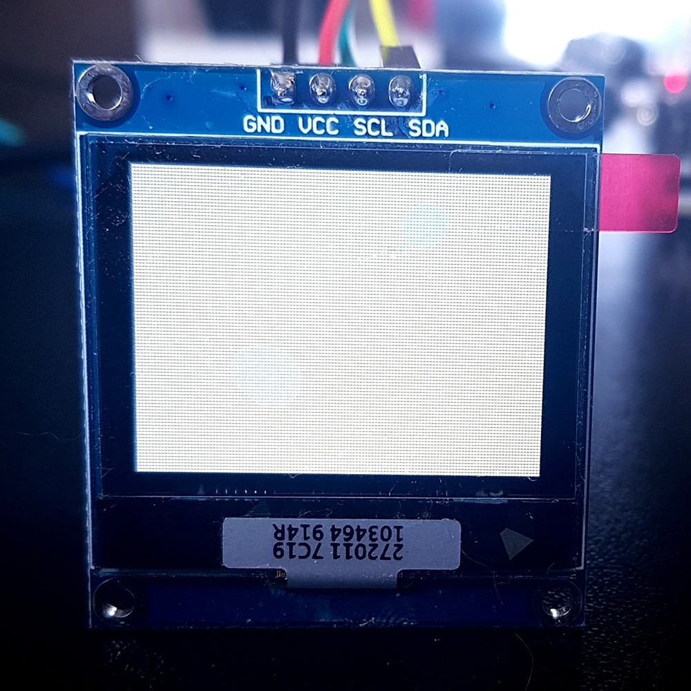
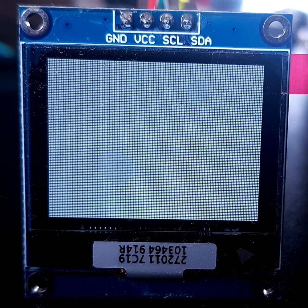
Let’s test it! All photos were taken with fixed camera settings.
Color: 15 (max). White.
Color 7 (middle). Yep, it’s gray.
Color 2 (almost black). Here you can hardly see anything anymore, but believe me that a slight glow is visible 🙂 This will be nicely visible e.g. in photos.
GFX library
You can use a library that is intended for monochrome displays. You just need to attach a pixel-drawing function and the display dimensions to the header.
#define GFX_DrawPixel(x,y,color) SSD1327_DrawPixel(x,y,color)
#define WIDTH SSD1327_LCDWIDTH
#define HEIGHT SSD1327_LCDHEIGHT
#define PIXEL_BLACK	BLACK
#define PIXEL_WHITE	WHITE
#define PIXEL_INVERSE	INVERSE
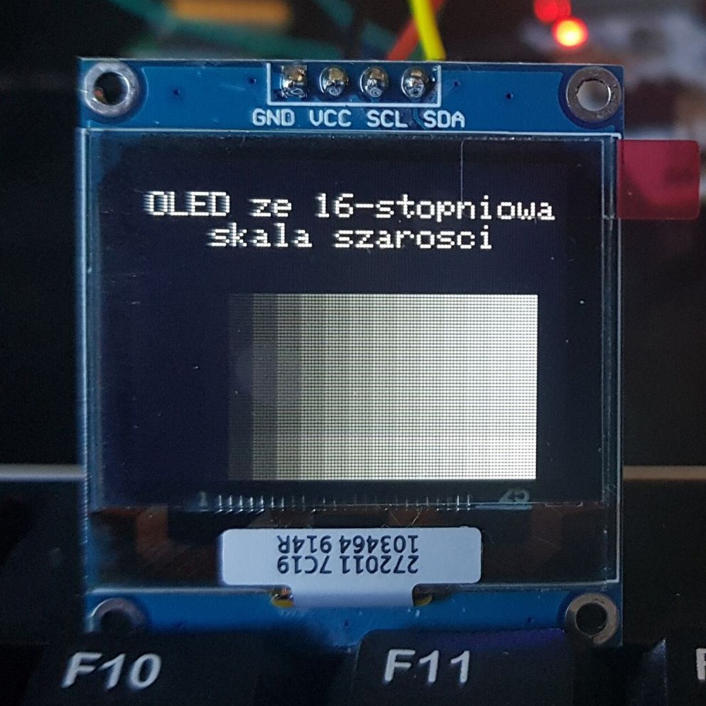
Then text and shapes work very well. Here is an example with drawing rectangles in all colors.
Unfortunately, drawing images will not work by default. Unfortunately, I wrote this library in such a way that it accepts only two colors—white and black. After all, it’s BW 🙂
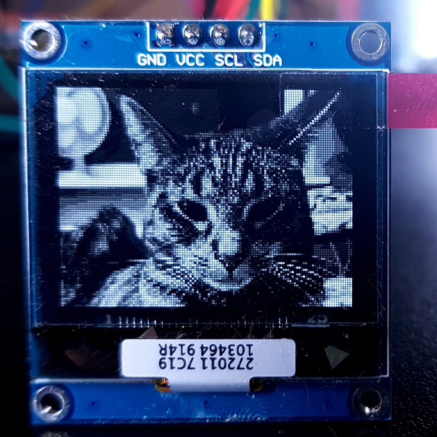
I’ll move on to generating and drawing images in the next posts. As a little teaser, here is what the msalamon.pl logo or a photo—e.g. my cat—looks like.
Summary
The pixel organization can give you something to think about, but if you think it through once and properly, you never have to do it again. Remember to write code in such a way that it helps you at later stages of writing the application.
Also, don’t be afraid to search the Internet and use other people’s work. Just be aware of what someone else’s code does 🙂
In the next post I’ll show you which program I use to generate bitmaps for microcontrollers. It’s a 100% free program and it can really do a lot!
Later we’ll upload such images to the microcontroller, and ultimately to the display.
You can find the full project together with the library, as usual, on my GitHub: LINK
If you noticed an error, disagree with something, would like to add something important, or simply feel like you’d like to discuss this topic, write a comment. Remember that the discussion should be polite and comply with the rules of the Polish language.
Table of contents for the entire SSD1327 OLED series:
In mid-July 2025, together with several leading creators from the embedded industry, we had the opportunity to visit the STMicroelectronics factory in Agrate, Italy. How did it happen? …well, I know 😅 This visit had Read more
UART Communication on STM32. Transmission to PC | STM32 on Registers #6 We have already learned the basic operations on GPIO, as well as ways to delay individual tasks. Today we will go beyond the Read more
Doing 3 Things at Once, or How to Implement a Software Timer? | STM32 on Registers #5 Let’s get to know one of the effective ways not to block the processor’s work by waiting. It Read more
The msalamon.pl blog uses cookies. By using the website, you consent to the use of cookies. More information can be found on the Privacy Policy page. Do not acceptAccept
Privacy Policy & Cookies
Privacy Overview
This website uses cookies to improve your experience while you navigate through the website. Out of these cookies, the cookies that are categorized as necessary are stored on your browser as they are essential for the working of basic functionalities of the website. We also use third-party cookies that help us analyze and understand how you use this website. These cookies will be stored in your browser only with your consent. You also have the option to opt-out of these cookies. But opting out of some of these cookies may have an effect on your browsing experience.


0 Comments