Not everyone may know this, but real-time clocks, or RTCs, are only as accurate as their clock source. Most often, such systems are driven by a 32.768 kHz frequency. STM32 has a built-in RTC, but exactly the same rule applies to its accuracy. Generally, what STM32 offers as an internal RC oscillator for the RTC is not of the highest quality and is susceptible to temperature changes. Connecting an
external quartz resonator also does not guarantee that it will operate identically at every possible temperature. Is there a solution? Yes – temperature compensation of the oscillator frequency.
But wait! You can compensate for frequency differences manually. Yes. You can perform oscillator frequency calibration. It’s a slightly complicated process and doesn’t guarantee results in all conditions. Using cheap quartz resonators doesn’t help either. Their error vs. temperature characteristic looks like this (from the STM32F103 RTC documentation):
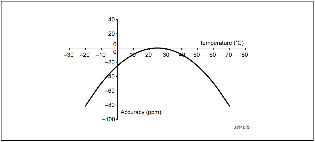
At an ambient temperature of about 0°C, the accuracy drops below -20 ppm. According to the calculator, an error at this level results in a delay of 1.73 seconds/day, i.e. 10.51 minutes/year. Who wants to set the clock every month? It’s less of a problem when the RTC has consistently similar conditions, such as in an apartment. Then you can save the day with software calibration. What if it’s in an outdoor device? Let’s say it’s installed in winter in an info booth with a huge, heat-generating display. On a sunny winter day, when the booth is open, the temperature in the electronics compartment might hit 40ºC at the extreme, giving an error of about -10 ppm. As evening approaches, the system cools down slowly moving left along the characteristic. Nice, because the error decreases for a while. Unfortunately at night, when the device is asleep, the temperature drops to -5ºC and the oscillator accuracy is -30 ppm. Are we able to perfectly compensate such errors in software? Probably we can, but who would want to…
Especially knowing that for little money you can get an RTC that compensates for such errors automatically. One of the precise chips on the market is the DS3231.
DS3231 – an extremely accurate RTC
Mr. Mateusz, how accurate is “accurate”? According to the documentation it is:
- ±2 ppm for temperatures 0 ÷ +40ºC
- ±3.5 ppm for temperatures -40 ÷ +85ºC
Entering 2 ppm into the calculator mentioned above shows that the DS3231 will be late by… a minute per year. Per day that’s 0.17 seconds. Is that acceptable? Much more than 10 minutes per year! This is a very good result.
How is it so accurate? The Maxim chip has an integrated quartz oscillator together with the crystal. The oscillator also has temperature compensation. This allows the manufacturer to control all the most important components that determine accuracy. Thanks to compensation, they squeeze the absolute maximum out of them, resulting in those ±2 ppm.
In Poland, detailed tests of DS3231 compensation were carried out by Mirek Kardaś. Allow me not to roast a chip connected to an oscilloscope 🙂
The most important things from the specification
Besides accuracy, you may be interested in a few other things. The most important is probably how the chip connects to the microcontroller. The communication interface is I²C, so it’s easy. In addition to the SDA and SCL pins, our RTC has a few other outputs.
As is typical with clock systems, we want the option to connect a battery to keep time. Here there is a dedicated pin, and inside the package there is a power-fail detection circuit and automatic switchover to battery power.
DS3231 has two clock outputs. One is 32.768 kHz straight from the built-in temperature-compensated oscillator and is called 32kHz. This source is perfect for clocking other circuits in low-power mode.
There is one more clock output. It is on a pin with a dual function called INT/SQW. Here we can get one of four programmable frequencies: 1 Hz, 1024 Hz, 4096 Hz, or 8192 Hz. This is a suitably divided oscillator frequency.
The second function of the INT/SQW pin, as the first part of the name suggests, is interrupts. According to the documentation, an interrupt is asserted when an alarm is active and its time arrives. Does anyone use alarms?
Importantly – both clock outputs are Open Drain. You need to provide pull-up resistors, which fortunately are already placed on the PCB in ready-made modules.
How are time and date stored? Of course, there are registers for hours, minutes, and seconds. As for the calendar, it is fairly extensive. In addition to year, month, and day, there is day of the week, century, and leap year support.
Schematics and software
Today I’ll use a Nucleo board with an STM32F410RB that I received from Kamami, for which I am very grateful! 🙂
Connecting the module to the Nucleo is, as usual, trivially simple. You only need to connect the I²C pins and the INT/SQW pin for the RTC interrupt.
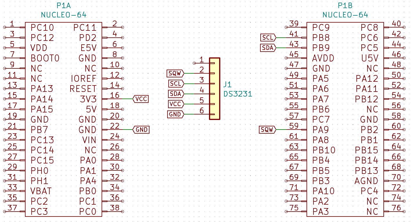
For the software I of course used STM32CubeIDE version 1.0.2. The HAL F4 libraries are version 1.24.1. Let’s go!
I could show you the classic approach, i.e., crude, blocking reads from the RTC every so often in the main loop. A better solution would of course be to read in the RTC interrupt, which occurs every second. However, such a crude, blocking read in an interrupt is also not optimal…
Remember that STM32 has something called DMA, of which I am a huge fan. You don’t have to wait idly while I²C communication is taking place. DMA can handle data collection, and the CPU can later convert BCD to DEC. I’ll show you a comparison at the end.
Configuring and handling DMA for the RTC
First, you need to configure the I²C interface. I chose I2C1. Choose the interface speed. I recommend 400 kHz, especially since the DS3231 supports Fast Mode. If your microcontroller cannot operate with that clock, the classic 100 kHz is fine. Use whichever pins you prefer. I set PB9 and PB8 because they are routed to the Arduino connector. That way I can connect a logic analyzer to the Morpho pins.
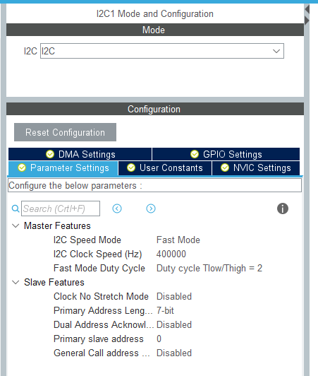
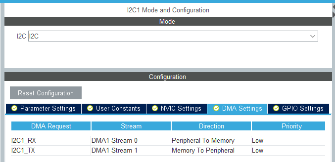
The next thing you need to set is DMA for our I2C1 interface. You can conveniently do this from the I²C configuration panel. Enable DMA for both receive and transmit.
To preview data from the RTC, also configure UART2 in the classic way, which is routed to the ST-Link USB. I leave the standard values, i.e., 115200 8n1.

You will also need a pin to handle the interrupt from the DS3231 chip. You can set any GPIO to the GPIO_EXTI function. I chose the PA9 pin. Name it DS3231_INT and set it to trigger on the falling edge. In practice it doesn’t matter which edge you choose 🙂 The important thing is to use one of the two so you don’t read the same time twice unnecessarily. Also remember to enable the interrupt for the proper EXTI in CubeMX!
You can leave the clock at the default 84 MHz if you generated the project “from the board” rather than by selecting the MCU. If you have it set differently, enter 84 for HCLK so our projects are consistent. After configuring the project like this, you can save it and generate the code. Also remember to select separate file generation for each peripheral.
Code
I prepared a simple library for the DS3231. It’s not a masterpiece that supports every function of the chip. I skipped alarms and reading the chip’s temperature (since there is temperature compensation, there is also the ability to measure temperature). I think the most important and useful part is reading the time and date anyway.
You’ll be interested in one or two defines. These are #define DS3231_USE_DMA and #define DS3231_ADDRESS (0x68<<1). The first, if uncommented, selects the function to read from the RTC via DMA. If it is commented out, it will work with the classic, blocking ones.
The second define is the chip address. The module without jumpers has address 0x68. If you have or placed jumpers, you will need to change this line according to your address.
Let’s move on to the functions that interest you. The first is of course initialization.
void DS3231_Init(I2C_HandleTypeDef *hi2c);
You pass in the handler of the selected I²C interface. Inside the initialization I set a 1 Hz waveform on the SQW output and disable the 32 kHz output.
The next important function is setting the clock.
void DS3231_SetDateTime(RTCDateTime *DateTime);
As an argument you pass a pointer to a previously prepared RTCDateTime structure, which is defined in the DS3231 library.
typedef struct
{
	uint16_t Year;
	uint8_t Month;
	uint8_t Day;
	uint8_t Hour;
	uint8_t Minute;
	uint8_t Second;
	uint8_t DayOfWeek;
}RTCDateTime;
The last important element is receiving data from the RTC and converting it into the RTCDateTime structure. Depending on which type of handling you choose, for blocking/interrupt-based you will have:
void DS3231_GetDateTime(RTCDateTime *DateTime);
This function will fetch the data via I²C and store it in the variable pointed to by *DateTime.
And the most important ones from the DMA perspective. Functions that receive data and place it into the structure.
void DS3231_ReceiveDateTimeDMA(void);
void DS3231_CalculateDateTime(RTCDateTime *DateTime);
Why two? I’ll explain.
DMA reception
I used the DS3231_ReceiveDateTimeDMA function in the EXTI interrupt generated by the RTC thanks to the 1 Hz signal on the SQW output. Its task is to start receiving from the DS3231 via DMA all the data related to time and date. Fortunately, RTC manufacturers place this data one after another.
When the reception is complete, a DMA reception complete interrupt is triggered. That’s where I placed the DS3231_CalculateDateTime function to unpack the received data into time and date values.
That’s all the philosophy 🙂 How to use these functions in interrupts? You need to override the default _weak functions provided by the HAL libraries. I did this in the main file, and it looks like this:
/* USER CODE BEGIN 4 */
void HAL_GPIO_EXTI_Callback(uint16_t GPIO_Pin)
{
  if(GPIO_Pin == DS3231_INT_Pin)
  {
    DS3231_ReceiveDateTimeDMA();
  }
}

void HAL_I2C_MemRxCpltCallback(I2C_HandleTypeDef *hi2c)
{
  DS3231_CalculateDateTime(&r);
}
/* USER CODE END 4 */
And that’s it! Simple, right?
Results, performance
If this isn’t your first time reading me, you know I like to check code execution times, especially CPU time. This time I won’t let it slide either!
First, I’ll show you what blocking data reception from the DS3231 looks like. First 100 kHz.

and 400 kHz

Hmm… 920 µs and 237 µs. Given that this code runs exactly every second, it’s easy to calculate that the read at 100 kHz takes 0.92% of CPU time, and for 400 kHz only 0.23%. Come on, Salamon, what more do you want from it?
Notice that the CPU is idly waiting for the data to be received over I²C. This means there is still a small room for improvement thanks to DMA. The effect of my DMA code looks like this:


100 kHz400 kHzNow there are two shorter segments during which the CPU is needed. The first is dispatching the DMA reception, the second is converting BCD to DEC and assigning to the struct variable. To calculate the CPU time, you need to sum them, which is simple. Thus, for 100 kHz the total is 301 µs, and for 400 kHz only 85 µs. Converted to % of CPU time, that’s 0.3% and 0.08%, respectively.
In both cases we have about a 3x gain. Not bad, right? An operation like reading the time should be as little burden on the system as possible. After all, it has more serious things to do.
Summary
I hope that if you weren’t already, you’re now convinced of the high accuracy of the RTC clock that is the DS3231. Although I feel that a comparison with other chips in terms of timekeeping accuracy would still be useful. I already have an idea 🙂
Admit it too, I’ve given you another reason to use DMA. Even in such – seemingly – trivial situations it’s worth doing.
And what do you think about such an RTC? Is it worth buying one? Surprisingly, modules are sometimes cheaper than other, less accurate chips that need several additional components around them. Check out the RTC modules in my store. By buying from me, you support the development of the blog and you get a cool sticker, e.g., for your laptop 😉
You’ll find the full project along with the library on my GitHub as usual: link
If you noticed any error, disagree with something, would like to add something important, or simply want to discuss the topic, leave a comment. Remember that the discussion should be polite and in accordance with the rules of the Polish language.
Podobne artykuły





0 Comments