Probably every one of my readers has dealt with some wearable device, the so-called wearables. Even the simplest fitness bands have a built-in heart rate sensor that most often measures at the user’s wrist. It turns out this isn’t some mysterious technology available only to a closed group of consumer electronics manufacturers. We can also perform a simple measurement of our own heart rate right at our desks. All it takes is the right circuit.
MAX30102 in healthcare
The company Maxim has released several sensors for heart rate measurement. One of them is today’s subject, the MAX30102 (
MAX30102 Datasheet
). In essence, it’s a 2-in-1 device because in addition to pulse it can also measure SpO2, i.e., blood oxygen saturation. This sensor is often used in smartphones, for example in Samsung devices.
The sensor requires 1.8 V to power the logic. In addition, a second voltage is required to power the LEDs. This can be 3.3 V, but the LEDs can also comfortably handle 5 V. The module has built-in LED power at 5 V, so you don’t need to worry about it.
This sensor has two built-in LEDs that illuminate the tissue being measured — one red and one infrared. A photodetector is used to capture the signal.
The device features very low current consumption of just 0.7 µA in Shutdown mode. The total current drawn by the sensor in active state mainly depends on the LED current, which is configured in software. Excluding the LEDs, the sensor itself needs about 600 µA to operate. Each LED current is software-controlled in the range 0–51 mA. Huh! 51 mA per LED seems quite a lot. I didn’t dare to push that much current…
The sensor has an INT interrupt output. It can be used to signal several events. In my opinion, the most useful ones are signaling a new sample and an approaching FIFO overflow.
Reflective heart rate and SpO2 measurement
The measurement used by our Max is called reflective because the LEDs and the photodetector are on the same side of the finger. Light emitted by the LEDs reflects off the finger (more precisely, the hemoglobin) and returns to the detector.
Blood oxygen saturation is measured thanks to the absorption of light by hemoglobin. Poorly oxygenated hemoglobin absorbs light at a wavelength of about 660 nm, while highly oxygenated hemoglobin absorbs more light at a wavelength of 940 nm. The LEDs built into the MAX30102 have wavelengths of 660 nm and 880 nm. Although they don’t hit the IR wavelength perfectly, it still works correctly. The oxygenation level is determined using the ratio of the light transmission for these two wavelengths.
The waveform of the reflected light has the pulse wave as its main component, from which it’s easy to read the pulse. Below I’ve included a plot for the red LED, captured from my finger using the sensor in question.
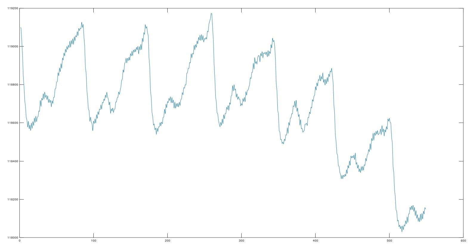
Diagram and CubeMX
Today I’ll use a Nucleo with the STM32F401RE.
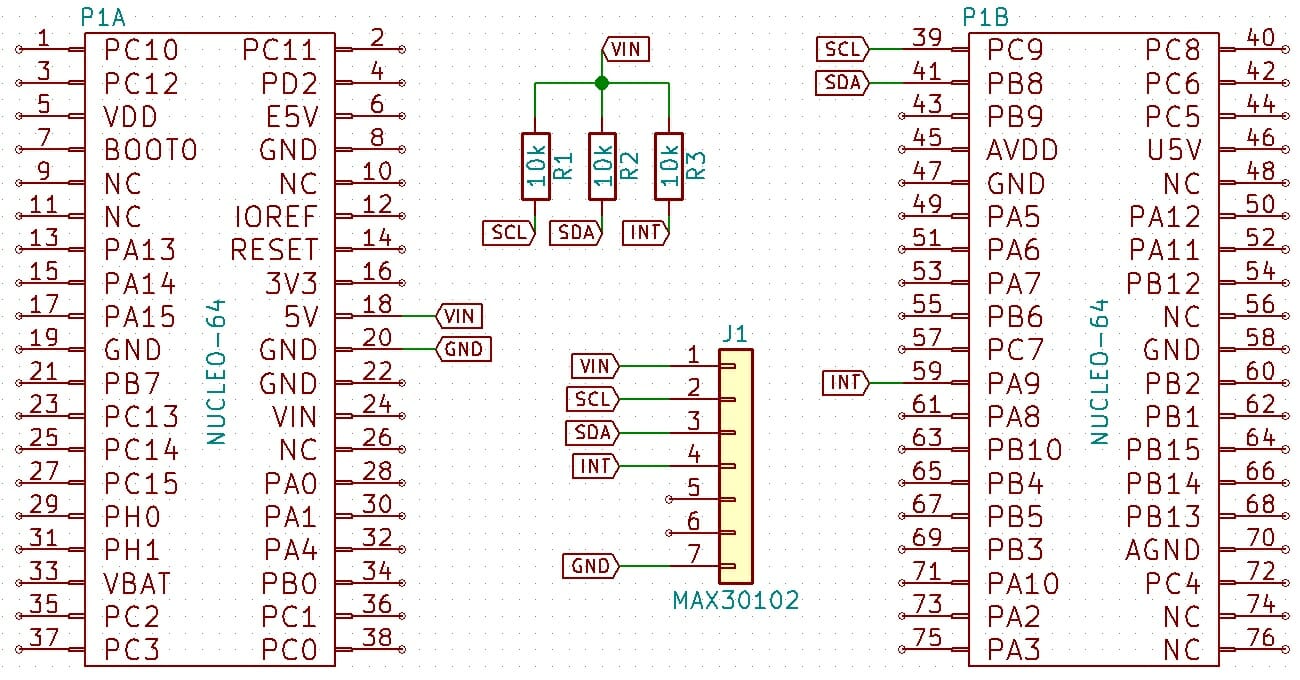
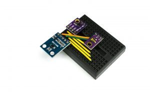
The sensor wiring diagram is simple thanks to the complete module we buy. Unfortunately, the pull-ups on the module are connected to 1.8 V, which doesn’t quite want to cooperate with an STM32 running at 3.3 V — at least not with my unit. That’s why I added external pull-ups to the module’s supply voltage, and configured the I2C and INT pins in the microcontroller as No pull-up and no pull-down.
Set I2C to 400 kHz right away.
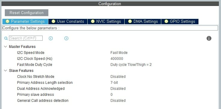
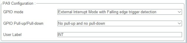
You also need an interrupt input reacting to a falling edge. Make sure Cube has enabled this interrupt during initialization. Sometimes it’s a pain. Preempting the comments – yes, yes, HAL is the worst in the world because of that 🙂
Library
Let’s move on to the most interesting part — how to use our sensor. Maxim provides example code on its site for Arduino and mbed. While the peak search algorithm, converting them to heart rate, and the algorithm calculating blood oxygenation are fine, the sample collection example is poor.
Unfortunately, the main example’s loop is dominated by waiting for an interrupt from the sensor. Then samples are fetched and processed. After first collecting 500, and then every 100 samples, the algorithm is run. In my opinion, the samples are needlessly shifted left after the calculations. A microcontroller should not sit and wait for an interrupt on purpose! In addition, the LEDs are always at full power, whether a finger is placed on the sensor or not. What a waste of current…
The example also won’t work with any configuration other than 100 samples per second. I fixed that.
I based my library on a simple state machine with four states, while samples are continuously collected in the interrupt. Samples go into a ring buffer, so you don’t need to shift them after every algorithm run. What happens in these wild machine states?
- MAX30102_STATE_BEGIN. The finger is not placed on the sensor. The red LED is off, IR at minimum. The IR LED is used to detect a finger on the sensor. Whenever the finger is removed from the sensor, the program returns to this state and turns off the LEDs.
- MAX30102_STATE_CALIBRATE. After placing the finger, the buffer needs to be filled with ‘valid data’. By default, calculations are performed on samples from the last 5 seconds. Calibration, i.e., filling the buffer, will therefore take that long.
- MAX30102_STATE_CALCULATE_HR. After collecting a sufficient number of samples, calculations are performed according to Maxim’s algorithm. In this step, the ring buffer is advanced by the number of samples corresponding to one second.
- MAX30102_STATE_COLLECT_NEXT_PORTION. In this state, the sensor handler remains until the next portion of samples (i.e., from the next second) is collected. After that it goes to state number 3 and the cycle repeats until the finger is removed from the sensor.
Using the library
I wrote the library to make it as simple to use as possible. It all boils down to a few steps. First, initialize the library and the sensor by passing which I2C interface is used.
MAX30102_STATUS Max30102_Init(I2C_HandleTypeDef *i2c);
The next important point is interrupt handling. You need to override HAL’s built-in weak function.
/* USER CODE BEGIN 4 */
void HAL_GPIO_EXTI_Callback(uint16_t GPIO_Pin)
{
	if (GPIO_Pin == INT_Pin)
	{
		Max30102_InterruptCallback();
	}
}
<!-- USER CODE END 4 -->
The last requirement is to put the function responsible for handling the state machine into the main loop.
void Max30102_Task(void);
Now you can read the current heart rate and oxygen saturation values from the library using two functions.
int32_t Max30102_GetHeartRate(void);
int32_t Max30102_GetSpO2Value(void);
Additional configuration
By default, the library and sensor are configured for a 5-second measurement and 100 samples per second. You can modify this freely. The library will automatically adjust buffer sizes for the samples and adapt the calculations.
Additionally, there’s a setting for the number of samples to trigger the FIFO Almost Full interrupt. If for some reason samples aren’t being received in time, they will be queued in the sensor. Queueing the configured number of samples will trigger the corresponding interrupt. Upon detecting this interrupt, the library will read all available samples in the buffer, clearing it at the same time. The buffer can hold up to 32 samples. The default value of 17 is the minimum that triggers the interrupt. For me this is sufficient, though I haven’t tested the sensor in a real battle. Perhaps in a more complex application the sensor will perform better with a higher value.
#define MAX30102_MEASUREMENT_SECONDS 5
#define MAX30102_SAMPLES_PER_SECOND 100 // 50, 100, 200, 400, 800, 100, 1600, 3200 sample rating
#define MAX30102_FIFO_ALMOST_FULL_SAMPLES 17
Demonstration
My example code prints the calculated values to the terminal.
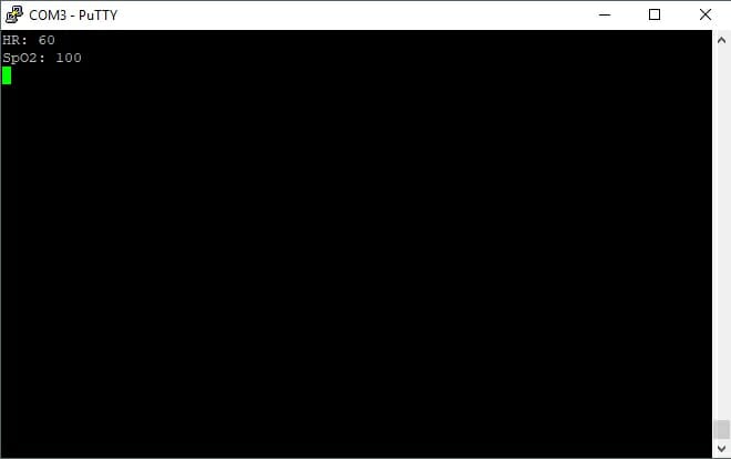
Pretty low heart rate for sitting and typing code. And I thought it was a stressful job 🙂 Also see how the LEDs are automatically turned on and off depending on whether a finger is placed on the sensor.
Summary
Maxim’s pulse oximeter is a very interesting device. It works correctly, although it will sometimes “stutter,” jumping with the computed heart rate. I’m not great at signal processing — I got a 3 in the lab 🙁 If someone could take a look at the algorithm code and improve it, I’d be immensely grateful! On the other hand, my smartphone behaves similarly, so perhaps it’s not the fault of a lame algorithm or my program.
Wearables today can measure heart rate at the wrist. Unfortunately, this sensor doesn’t do well in that location. I dug into a bit of theory and for wrist measurements one more, green LED is recommended. You can see this e.g. in the fitness bands or running watches mentioned at the beginning. I think this sensor — just like on a phone — can be treated more as a curiosity than a precise measuring instrument. Continuous finger measurement might only be useful in a hospital. I don’t see much use for myself. Maybe you do? Share it in the comments!
The full project along with the library can be found, as usual, on my GitHub: link
If you’ve noticed any mistake, disagree with something, would like to add something important, or just feel like discussing this topic, write a comment. Remember that the discussion should be polite and in accordance with the rules of the Polish language.
If you liked the sensor, you can get it in my store.
Contest results from the previous post
Recently I reviewed the book “Mikrokontrolery STM32 dla początkujących,” which is based on the HAL libraries I use. On this occasion I organized a contest in which 4 sets of the book + KA-NUCLEO-F411CEv2 evaluation board were up for grabs. Without further ado, here are the winners I selected:
1. Szymon Fronc with the comment:
A review just as it should be — concise and to the point — building appetite and willingness to embark on an adventure with something that for someone like me is a further step in playing with microcontrollers. I think STMs can broaden horizons (something new beyond the Arduino I’ve used so far), which I would gladly try if I managed to snag such a set for myself. Time to enter the contest
Best regards and I’m waiting for more interesting reviews!
2. Mateusz with the comment:
A good, factual review that primarily encourages the “freshmen gang” to start their adventure with STM microcontrollers and frankly discourages more experienced programmers from the book. I myself have been into AVR family microcontrollers for a long time and I must admit I’ve been approaching STMs like a dog approaches a hedgehog! It’s great that there are people who infect others with their passion. Thank you and best regards!
3. Franek with the comment:
A good review, it’s clear the author is actually experienced in the subject and is interested in the book. Also a big plus that it’s an honest review showing the book from the perspective of its flaws and explicitly stating who its audience is.
4. Norbert with the comment:
The review certainly encouraged me to take part in the contest; perhaps it will translate into approaching the “monster” that is the vast capabilities of STM32 microcontrollers. If you present a cross-section starting from beginner proposals to the more advanced — I’m all in for such publications.
Congratulations! I’ll contact you by email to finalize the contest. Cheers!
Podobne artykuły





0 Comments