It’s time to use MAX7219 in a slightly different way than it was probably originally designed for. We will create graphic LED displays controlled by a higher-level graphics library. This will work exactly the same way as, for example, OLEDs. See how simple it is 🙂

Complete post series:
No more multiplexing on GPIO! MAX7219 in action part 1
No more multiplexing on GPIO! MAX7219 in action part 2
No more multiplexing on GPIO! MAX7219 in action part 3
MAX7219 – matrix multiplexing
The fact that these chips are intended for 7-segment displays doesn’t mean they can’t be used differently. The digit decoder can be disabled, and then the data can be written freely. Since one digit means 8 LEDs and the chip controls eight digits, the math is simple – we can drive 64 LEDs in any way. Of course, our friends from China have made sure you don’t have to struggle with wiring these diodes. There are 8×8 pixel matrices with common cathode available, which are multiplexed in the same way as ordinary 7-segment displays. The LEDs are just arranged differently.
You can buy single, double, or quad modules. All are chained, which makes the whole connection easier. Each subsequent module is also connected in cascade, so data transmission looks the same as for digits, with the difference that now we have a graphic display.
Since these are individual pixels, why not use these matrices just like, for example, an OLED I wrote about some time ago. The idea is to use the GFX_BW library, which is used to draw simple graphics and bitmaps very easily.
How is the matrix wired?

As you remember, with the OLED we worked on a RAM buffer that mirrored what was to be on the display. For MAX7219 matrices I did the same. GFX_BW needs only a function that sets a single pixel to operate. Pixel (0,0) is located in the top-left corner of the display. As a reminder – X increases to the right, and Y downward.
So how does the MAX7219 accept data when used with matrices? I think the drawing explains it best.
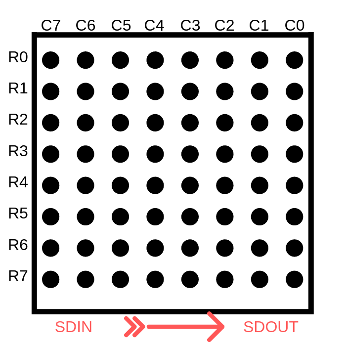
R[0÷7], i.e. rows – are the subsequent digits that are written into the MAX7219. C[0÷7], on the other hand, are the corresponding bits contained in each digit (the transmitted byte). To sum up. To set pixel (0,0) you must set the seventh bit of digit zero in the MAX7219. To set, for example, pixel (4,2) you must light BIT3 of the second digit.
Now it’s enough to properly assign this data to the buffer that will be pushed to the MAX7219 chips. During tests I discovered that there are two types of modules on the market 🙁 They differ in almost nothing. Well, almost. There is one small detail – the connections between the IC and the LED matrix are different. They are exactly as in the drawing below.
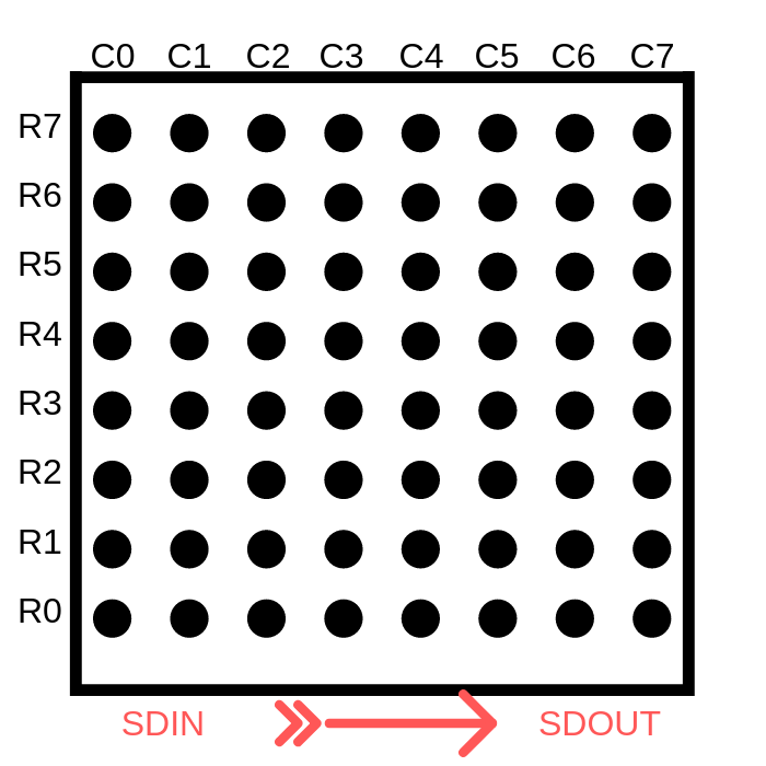
The difference lies in a mirror connection of digits and their bits. A bit like swapping little-endian to big-endian or vice versa. This makes the buffer fill based on the first connection incorrect for the second one and, as a result, text and images are displayed incorrectly, as I reported on my fanpage.
Fortunately, I handled this at the level of the pixel-setting function, so the higher layers are completely unaffected.
Ultimately, the pixel drawing function looks like this:
MAX7219_STATUS MAX7219_SetPixel(int x, int y, MAX7219_Color Color)
{
	if ((x < 0) || (x >= MAX7219_X_PIXELS) || (y < 0) || (y >= MAX7219_Y_PIXELS))
		return MAX7219_OUT_OF_RANGE;
	switch(Color)
	{
		#if(MAX7219_MODULE_TYPE == 0)
		case MAX7219_WHITE: Max7219PixelsBuffer[(x/8) + (y*MAX7219_COLUMNS)] |= (0x80 >> (x&7)); break;
		case MAX7219_BLACK: Max7219PixelsBuffer[(x/8) + (y*MAX7219_COLUMNS)] &= ~(0x80 >> (x&7)); break;
		case MAX7219_INVERSE: Max7219PixelsBuffer[(x/8) + (y*MAX7219_COLUMNS)] ^= (0x80 >> (x&7)); break;

		#elif(MAX7219_MODULE_TYPE == 1)
		case MAX7219_WHITE: Max7219PixelsBuffer[(x/8) + ((MAX7219_PIXELS_PER_DEVICE_ROW-1) - ((y%8)) + ((y/8)*MAX7219_PIXELS_PER_DEVICE_ROW))*MAX7219_COLUMNS] |= (1 << (x&7)); break;
		case MAX7219_BLACK: Max7219PixelsBuffer[(x/8) + ((MAX7219_PIXELS_PER_DEVICE_ROW-1) - ((y%8)) + ((y/8)*MAX7219_PIXELS_PER_DEVICE_ROW))*MAX7219_COLUMNS] &= ~(1 << (x&7)); break;
		case MAX7219_INVERSE: Max7219PixelsBuffer[(x/8) + ((MAX7219_PIXELS_PER_DEVICE_ROW-1) - ((y%8)) + ((y/8)*MAX7219_PIXELS_PER_DEVICE_ROW))*MAX7219_COLUMNS] ^= (1 << (x&7)); break;

		#endif

		default: return MAX7219_ERROR;
	}
	return MAX7219_OK;
}
You choose which kind of module you will be dealing with via the MAX7219_MODULE_TYPE constant. Type set to 0 is the first one I showed – more human-friendly. If you have the second module, set this constant to 1.
Library settings
Besides the matrix type mentioned above, you need to set a few more constants.
First, the number of devices, i.e. how many MAX7219 chips you have in the setup. For a chain of 7-segment displays this was one value. Here I made two:
- Number of rows – MAX7219_ROWS
- Number of columns – MAX7219_COLUMNS
You can connect matrices not only one after another, but also one below another. There is one condition that must be met for the library to work correctly. You MUST connect the DOUT of the last chip in a row to the first chip in the next row.
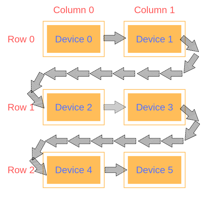
Based on the drawing you can also see how to set the number of devices. We have 3 rows and 2 columns. So in the header file it will look like this.
//
// Configuration
//
#define MAX7219_ROWS 3
#define MAX7219_COLUMNS 2
The last setting is the decision whether you use hardware control of the CS pin. I also described this in the OLED post.
Alright, but what about the resolution and, therefore, the buffer size. I decided these settings would calculate themselves based on the number of chips in the system. Knowing that each device has 8×8 pixels, and how many devices there are in each direction, it’s easy to calculate the resolution of the entire display. Everything is handled by convenient macros
//
// Resolution
//
#define MAX7219_PIXELS_PER_DEVICE_ROW 8
#define MAX7219_PIXELS_PER_DEVICE_COLUMN 8
#define MAX7219_X_PIXELS (MAX7219_PIXELS_PER_DEVICE_ROW*MAX7219_COLUMNS)
#define MAX7219_Y_PIXELS (MAX7219_PIXELS_PER_DEVICE_COLUMN*MAX7219_ROWS)
#define MAX7219_DEVICES (MAX7219_ROWS * MAX7219_COLUMNS)
Library functions
Besides the standard initialization, you have 3 functions at your disposal that you will use intensively.
MAX7219_STATUS MAX7219_SetPixel(int x, int y, MAX7219_Color Color);
MAX7219_STATUS MAX7219_Clear(MAX7219_Color Color);
MAX7219_STATUS MAX7219_Display(void);
MAX7219_SetPixel for setting a pixel, which you pass to the higher-level GFX_BW library.
MAX7219_Clear for clearing the RAM buffer to a specified color.
MAX7219_Display for transferring the RAM buffer to the display.
We don’t need anything else. GFX_BW handles the rest.
Display operation
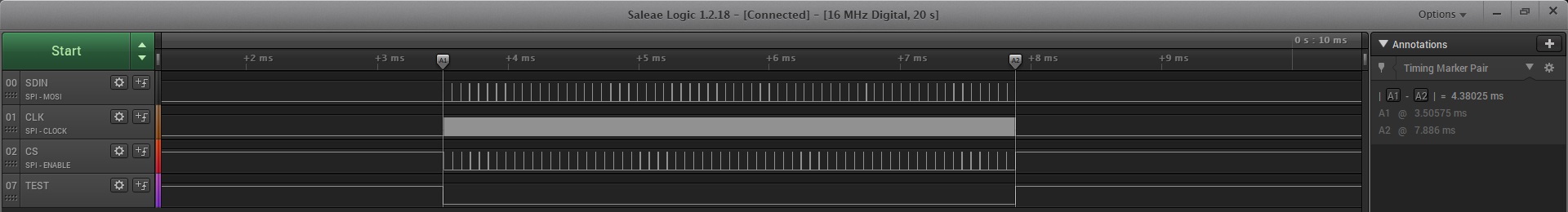
I took two modules with 4 MAX7219 chips each onto my desk. Connected one after another, they build a display with a resolution of 64 x 8 pixels. There are as many as 8 devices to configure, and each “digit” in the MAX7219 chips is always set, even if no pixel changes. Therefore, refreshing the entire display will take a little while. Let’s see how long.
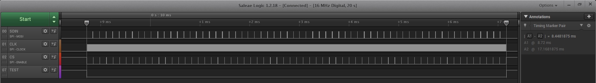
SCK 1.25 MHz
SCK 2.5 MHz

SCK 5 MHz
SCK 10 MHz
- Clock 1.25 MHz – 8.45 ms
- Clock 2.5 MHz – 4.38 ms
- Clock 5 MHz – 2.34 ms
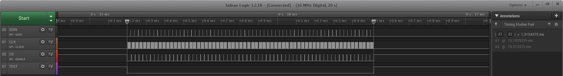
- Clock 10 MHz – 1.32 ms
The differences between the results are as expected. Alright, but this probably doesn’t tell you much. I’ll now set as many devices as needed to get a resolution of 128 x 64, as in the case of OLEDs. That will be 16 x 8 devices, i.e. a total of 128 MAX7219 chips. I don’t have that many, but the SDIN pin will still carry the signal for them 🙂
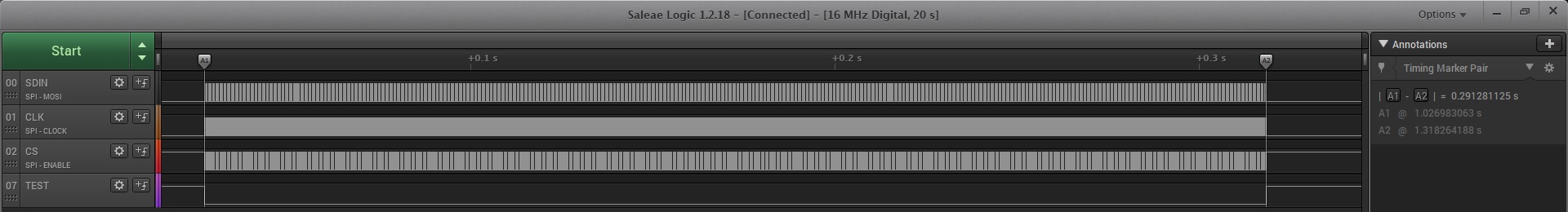
So what?! As much as 291 ms! Disaster… What do I need a display for if I can refresh it only 3 times per second… Can this be sped up? What if I wanted to build a matrix several times larger?!
Speed up!
Such slow operation is unacceptable. The problem is that we perform only one assignment to one chip at a time, while No-ops are sent to the others. In this way, when sending information to 128 chips, we set only 8 pixels out of 8192. As you can easily calculate, you need to send information about eight pixels to all 128 MAXs 1024 times.
How can this be sped up? You can eliminate those unfortunate No-ops. Instead of sending zeros to almost all chips, always send useful information to each of them. You can send data for digit zero to each one in a single go. Then for the first digits, second digits, etc. In this way we will transfer data for 128 devices only 8 times!
To do this, the MAX7219_Display function needs to be modified so that it does not send data to individual chips, but packs into its buffer the data for each MAX and then pushes it via SPI.
Of course, I managed to modify the code in this way. For the test eight chips, sending the entire frame takes several times less time.

SCK 1.25 MHz
SCK 2.5 MHz

SCK 5 MHz
SCK 10 MHz
- Clock 1.25 MHz – 1.06 ms
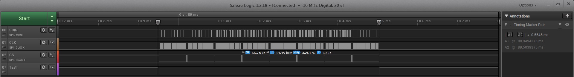
- Clock 2.5 MHz – 0.55 ms
- Clock 5 MHz – 0.29 ms
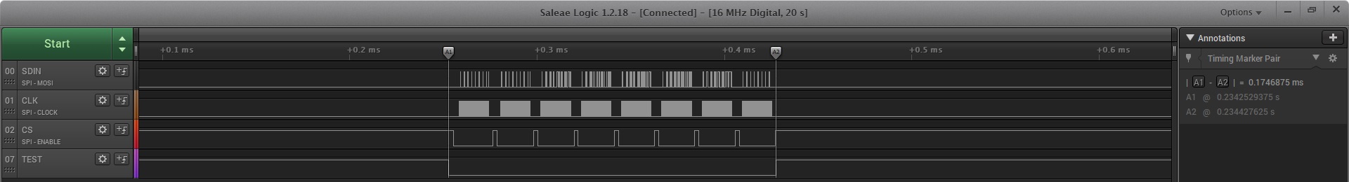
- Clock 10 MHz – 0.175 ms
A beautiful reduction in refresh time. I’ll just take a look at how it looks for 128×64 resolution and 10 MHz on the clock:
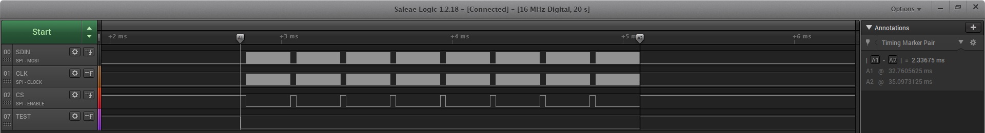
BOOM! Only 2.34 ms. That’s over a hundredfold gain!
I’ll compile all the data I’ve collected so you have a convenient comparison.
| 8 IC (64 x 8 px) | 8 IC (64 x 8 px) optimized | 128 IC (128 x 64 px) | 128 IC (128 x 64 px) optimized | |
|---|---|---|---|---|
| 1.25 MHz | 8.45 ms | 1.06 ms | 2.13 s | 16.70 ms |
| 2.5 MHz | 4.38 ms | 0.55 ms | 1.08 s | 8.50 ms |
| 5 MHz | 2.34 ms | 0.30 ms | 554 ms | 4.39 ms |
| 10 MHz | 1.32 ms | 0.175 ms | 291 ms | 2.34 ms |
And this is how it looks in action.
Summary
Of course, this code can be further improved if needed, for example with DMA. As for me, I would end this series of posts about MAX7219 here. Honestly, I didn’t think it would turn into as many as three posts. These chips seemed trivial to me, but as I delved into them I had a lot of fun improving the code. I hope that while reading you had at least half as much fun as I did, huehue 🙂
MAX7219 is a great integrated circuit. If you can put it into your project, I recommend it as a replacement for classic GPIO multiplexing. There’s no point struggling with code optimization. Let me know in the comments what you think about these chips.
The full project along with the library can be found, as usual, on my GitHub: link
If you noticed any error, disagree with something, would like to add something important, or simply think you’d like to discuss this topic, write a comment. Remember that the discussion should be polite and in accordance with the rules of the Polish language.
Podobne artykuły


0 Comments