Blinking an LED on STM32, GPIO Output
Recently, we learned how to set up an STM32 project for register-level programming. This time I’ll show you how to blink an LED 😎
In today’s post we’ll go through configuring GPIO Output and learn how to control the output of a single GPIO pin. For the exercises we’ll use the built-in LD4 LED located on the NUCLEO-C031C6.

STM32 on Registers series on YouTube
These posts are created in parallel with the series on my YouTube on the same topic. If you prefer the video version, I invite you there. These articles are a condensed version of what I show on YouTube.
Configuring GPIO Output on STM32
I start the work from an empty project that I created in the previous article. First, we need to find out which pin of the microcontroller the LED on the NUCLEO-C031C6 board is connected to. The easiest way here will be to use the schematic. You can find the schematic on the Nucleo page in the CAD Resources tab. Link to our schematic.
What we care about is on page 4 and looks as follows:
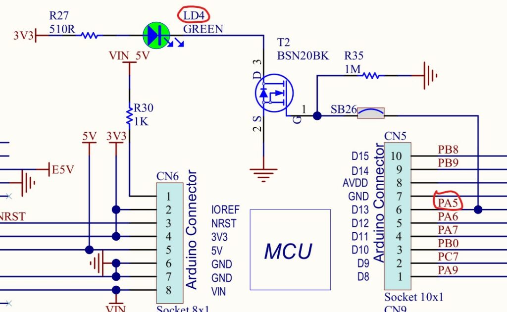
The LD4 LED is connected through an N-MOSFET to pin PA5 on GPIOA. This means that turning the LED on will force a high state on the transistor gate, and turning it off – a low state.
Peripheral clocks
STM32s are built in such a way that each peripheral needs its own clock. Each GPIO port, in turn, has separate clocking.
Clock control is handled by the RCC block (Reset and Clock Control), and it is there that we must enable the clock. In our case, for GPIOA. I show the detailed way of working with the documentation on YouTube. Here in the article I will paste ready-made code that you need to type in to get the effect.
To enable the clock for GPIOA in the STM32C031C6T6 you need to write
// Enable Clock for PORTA
RCC->IOPENR |= RCC_IOPENR_GPIOAEN;
WARNING! Other STM32s may have the GPIO clock enable bits in different RCC registers. You have to confirm it every time in the Reference Manual!
Pin configuration
Once we have clocking on GPIOA, we can move on to its configuration. Previously this peripheral was inactive and we wouldn’t be able to do anything. What do we need to set?
We are interested in a few registers:
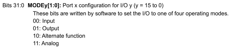
- MODER – here we set the mode in which specific GPIO pins operate. Here we decide whether a given pin is Input / Output / Alternate Function / Analog Input
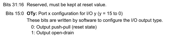
- OTYPER – Output type. Here we indicate whether we want push-pull output or open-drain
- OSPEEDR – Output edge rise speed. This parameter says how steep the edge should be when changing state. Useful when minimizing and optimizing various kinds of interference
- PUPDR – the register where we enable (or not) the built-in pull-up and pull-down resistors. Register values differ between families and you must verify this in the Datasheet.
Our LED is on PA5. So we’re interested in the set of these registers for GPIOA and the settings for number 5. Sometimes these will be single bits, sometimes a couple. What do we need to set?
Pay attention to one thing that is in the Reference Manual for each register.
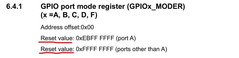
All microcontroller registers after reset have a specific, predefined value. This means that you won’t have to configure all registers during the initial setup right after the microcontroller starts.
For now we’ll set everything. So that I can show you the full configuration and leave no ambiguity.
MODER – here we set GPIO Output, i.e. value 0b01.
// Configure GPIO Mode - Output
GPIOA->MODER |= GPIO_MODER_MODE5_0;
GPIOA->MODER &= ~(GPIO_MODER_MODE5_1);
OTYPER – LEDs whose cathode is directly connected to a GPIO pin should be driven in push-pull mode. Here we have a MOSFET, which additionally has some pull-up that eliminates floating states and charges the gate. Let’s use push-pull here. It doesn’t matter that much what we choose, because the built-in pull-up resistor would outweigh the hardware one anyway.
Push-pull is already set after reset, so this setting is redundant.
// Configure Output Mode - Push-pull
GPIOA->OTYPER &= ~(GPIO_OTYPER_OT5);
OSPEEDR – It’s worth keeping the rise speed as low as possible. Sometimes you can’t, because you need to implement a fast custom interface on GPIO. Blinking an LED is slow, so we can set the lowest possible, i.e. Low. It is set by default after reset.
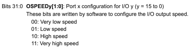
// Configure GPIO Speed - Low
GPIOA->OSPEEDR &= ~(GPIO_OSPEEDR_OSPEED5);
PUPDR – We’re using push-pull output. Enabling built-in pull-ups doesn’t make much sense. We must disable them, which is basically the default state after reset.
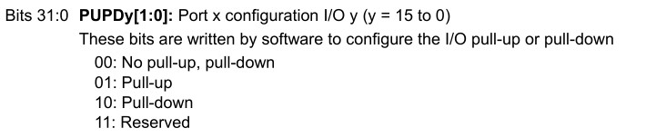
// Configure Pull-up/Pull-down - no PU/PD
GPIOA->PUPDR &= ~(GPIO_PUPDR_PUPD5);
Finally, it’s worth wrapping the entire LED configuration in a convenient function whose name says what it’s for.
void ConfigureLD4(void)
{
	// Enable Clock for PORTA
	RCC->IOPENR |= RCC_IOPENR_GPIOAEN;

	// Configure GPIO Mode - Output
	GPIOA->MODER |= GPIO_MODER_MODE5_0; // It's default reset state. Not necessary.
	GPIOA->MODER &= ~(GPIO_MODER_MODE5_1);

	// Configure Output Mode - Push-pull
	GPIOA->OTYPER &= ~(GPIO_OTYPER_OT5); // It's default reset state. Not necessary.

	// Configure GPIO Speed - Low
	GPIOA->OSPEEDR &= ~(GPIO_OSPEEDR_OSPEED5); // Two bits together. It's default reset state. Not necessary.

	// Configure Pull-up/Pull-down - no PU/PD
	GPIOA->PUPDR &= ~(GPIO_PUPDR_PUPD5); // It's default reset state. Not necessary.
}
Controlling the GPIO output
To control what is present on the GPIO Output pin, we have two (or even three!) methods.
The first is the “regular” one via the ODR register (Output Data Register). We write the state we want to the position of our pin. Here we have to remember not to change the state of the other outputs. Because of that it has a drawback in the form of complexity. We must perform several operations (read the register, change one bit, write it back) to change a single bit.
The second method is atomic access, i.e. performed in a single operation (the write itself). This method is based on a special BSRR register. It only reacts to writing a one, so bits that are zero remain without effect.
BSRR is 32-bit and is split in half. The upper half corresponds to resetting the appropriate pin, the lower half to setting it. So with the upper 16 bits we set 0 on the indicated pin, and with the lower bits we set 1. These actions are reflected in the ODR register.
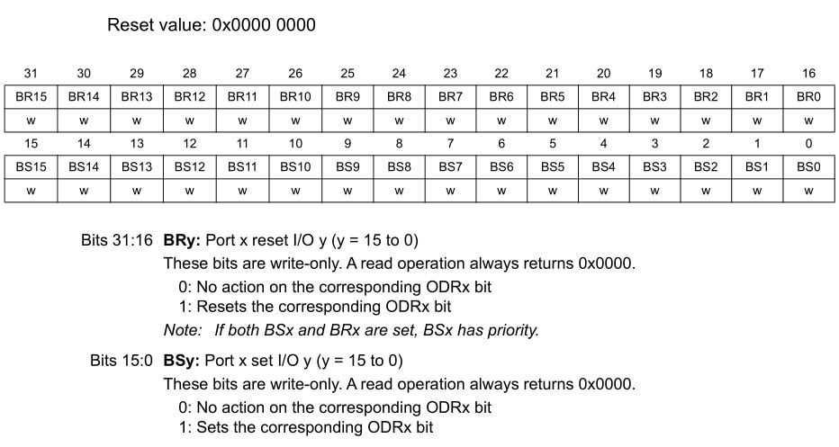
We’ll use atomic access. It is much more efficient and effective. To set a high state on pin PA5 we must write a one to the BSRR register on the bit marked as BS5 (Bit Set).
NOTE. On YouTube I made a mistake… we only need to write a one to the pin we care about. The other ones don’t matter to us, and writing a zero does not change the output state. That’s why we do a direct assignment, without any logical operation. That guarantees atomic access 👍
GPIOA->BSRR = GPIO_BSRR_BS5
To get a low state on PA5, we write a one to BSRR at bit position BR5 (Bit Reset), i.e. bit 21 of this register.
GPIOA->BSRR = GPIO_BSRR_BR5
And this is how we can control the LED. It would be nice to also create convenient macros that immediately tell us what they do.
#define LD4_ON GPIOA->BSRR = GPIO_BSRR_BS5
#define LD4_OFF GPIOA->BSRR = GPIO_BSRR_BR5
Blinking the LED – delay
Blinking an LED consists of cyclically turning the LED on and off. A microcontroller is a very fast beast. For us to see the blinking at all, we must delay these two cyclic operations.
We’ll deal with proper delaying in the next lessons, but today we’ll use a dumb delay based on for loops.
void Delay(void)
{
	uint32_t i;

	for(i = 0; i < 99999; i++)
	{

	}
}
It has many drawbacks, such as not controlling the delay time easily, and the fact that this loop can be optimized away when compiler optimization is enabled. For today, however, it will be enough 😎
In main, we now need to first call the function that configures the LD4 LED pin, and in the infinite loop put turning the LED on and off, separated by our dumb delay. It will look like this:
int main(void)
{

	ConfigureLD4();

    /* Loop forever */
	while(1)
	{
		// Set LED on PA5
		LD4_ON;
		Delay();

		// Reset LED on PA5
		LD4_OFF;
		Delay();
	}
}
After compiling and flashing to our Nucleo, you’ll see a blinking LED!
The complete code for convenient viewing:
#include "main.h"

#define LD4_ON GPIOA->BSRR = GPIO_BSRR_BS5
#define LD4_OFF GPIOA->BSRR = GPIO_BSRR_BR5

// PA5 - LD4

void ConfigureLD4(void);
void Delay(void);

int main(void)
{

	ConfigureLD4();

    /* Loop forever */
	while(1)
	{
		// Set LED on PA5
		LD4_ON;
		Delay();

		// Reset LED on PA5
		LD4_OFF;
		Delay();
	}
}

void ConfigureLD4(void)
{
	// Enable Clock for PORTD
	RCC->IOPENR |= RCC_IOPENR_GPIOAEN;

	// Configure GPIO Mode - Output
	GPIOA->MODER |= GPIO_MODER_MODE5_0; // It's default reset state. Not necessary.
	GPIOA->MODER &= ~(GPIO_MODER_MODE5_1);

	// Configure Output Mode - Push-pull
	GPIOA->OTYPER &= ~(GPIO_OTYPER_OT5); // It's default reset state. Not necessary.

	// Configure GPIO Speed - Low
	GPIOA->OSPEEDR &= ~(GPIO_OSPEEDR_OSPEED5); // Two bits together. It's default reset state. Not necessary.

	// Configure Pull-up/Pull-down - no PU/PD
	GPIOA->PUPDR &= ~(GPIO_PUPDR_PUPD5); // It's default reset state. Not necessary.
}

void Delay(void)
{
	uint32_t i;

	for(i = 0; i < 99999; i++)
	{

	}
}
Summary
Configuring and using GPIO isn’t as difficult as it might initially seem. It becomes problematic if we don’t know what to do. That’s why this series is being created 🙂 Now you’ll have no problem dealing with other GPIO pins, also on other ports.
In the next post we’ll take care of that ugly delay. We’ll replace it with a controlled one using the SysTick Timer. It still won’t be the prettiest delay, but at least it will be controllable.
Let me know in the comments if you liked this post! Maybe you have a suggestion of what to show as part of the STM32 on Registers cycle? Share this article with your friends.
I also invite you to my shop, where you can buy interesting electronics for programming such as the NUCLEO-C031C6 that we use in this series: https://sklep.msalamon.pl
You can find the project from this article at: https://github.com/lamik/stm32narejestrach_2
Podobne artykuły


0 Comments