The RTC clock you’ll find in STM32 microcontrollers is used not only for simple timekeeping. Besides this basic function, it also has several other more or less useful ones. I’ve already shown you the backup registers, which can be used to store sensitive data or remember the date in a less advanced clock. This time I’d like to show you a few other features that are available to us.
While writing, it turned out I produced quite a lot of text, so I split this post into two parts 🙂
Additional RTC features in STM32F4
You may remember from the previous post that in the F4 series there are really quite a lot of registers in the real-time clock module itself. This is caused, among other things, by the fact that we have a few interesting functions added. I’ll show you the first two related to “break-ins”:
- Tamper
- Time Stamp
- Tamper + Time Stamp
Let me base this on the board I chose in the previous article. It’s the so-called BlackPill with STM32F401 onboard. You can buy such a board (or a slightly more powerful one) from me.

The software I’ll use is:
- STM32CubeIDE v1.2.0
- STM32CubeMX v5.5.0 built into the IDE
- HAL F4 v1.24.2
I’ll also base this on the project I created for STM32F4.
Time Stamp in STM32F4
Translating this into Polish, it would be “Stempel Czasu” (like from Harry Potter, darn it). This function works such that during a “break-in”, i.e., when an edge is detected on a dedicated pin, the date and time are latched. This is done “silently”, so the intruder won’t realize what happened.
We can immediately send such registered tampering remotely to headquarters or store it in logs in non-volatile memory.
First, you need to enable this function in Cube by checking it.
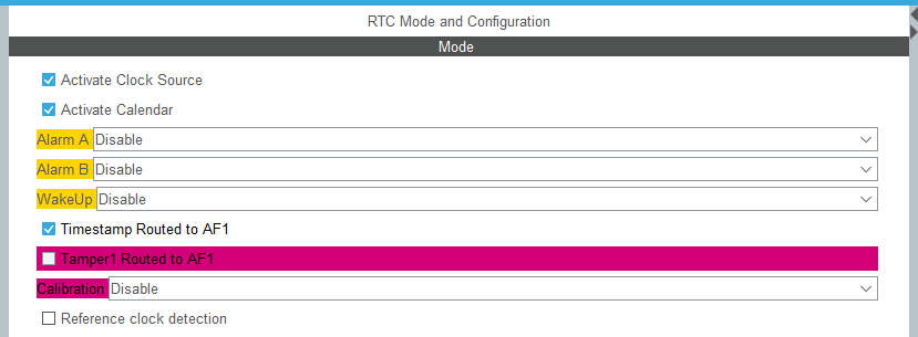
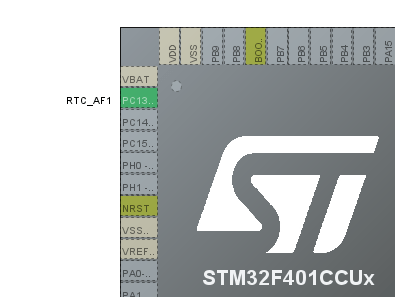
A configured GPIO pin will appear on PC13. It will serve as the stamp source.
An additional section will appear in the RTC configuration.

Select which edge you’re interested in here. I chose the falling edge. On pin PC13 I additionally added a 10 kΩ pull-up resistor to supply. You can’t set an internal Pull Up for a special pin.
The Event Time Stamp generates an interrupt. Of course, in HAL we’ll find its handler that we can implement. In it, I read the date and time of the occurrence and set my own flag, which I’ll use in the main loop.
void HAL_RTCEx_TimeStampEventCallback(RTC_HandleTypeDef *hrtc)
{
  HAL_RTCEx_GetTimeStamp(hrtc, &RtcTimeStamp, &RtcDateStamp, RTC_FORMAT_BIN);
  MillisecondsStamp = ((RtcTime.SecondFraction-RtcTimeStamp.SubSeconds)/((float)RtcTime.SecondFraction+1) * 100);
	TimeStampFlag = 1;
}
I use this flag in the main loop to print the stamp date and time. The rest of the time, every second I send data from the RTC to the serial port.
  /* USER CODE BEGIN WHILE */
  while (1)
  {
	  HAL_RTC_GetTime(&hrtc, &RtcTime, RTC_FORMAT_BIN);
	  Milliseconds = ((RtcTime.SecondFraction-RtcTime.SubSeconds)/((float)RtcTime.SecondFraction+1) * 100);
	  HAL_RTC_GetDate(&hrtc, &RtcDate, RTC_FORMAT_BIN);

	  if(RtcTime.Seconds != CompareSeconds)
	  {
		  MessageLen = sprintf((char*)Message, "Date: %02d.%02d.20%02d Time: %02d:%02d:%02d:%02d\n\r", RtcDate.Date, RtcDate.Month, RtcDate.Year, RtcTime.Hours, RtcTime.Minutes, RtcTime.Seconds, Milliseconds);
		  HAL_UART_Transmit(&huart2, Message, MessageLen, 100);
		  CompareSeconds = RtcTime.Seconds;
	  }

	  if(TimeStampFlag == 1)
	  {
		  MessageLen = sprintf((char*)Message, "TimeStamp! Date: %02d.%02d.20%02d Time: %02d:%02d:%02d:%02d\n\r", RtcDateStamp.Date, RtcDateStamp.Month,
				  RtcDateStamp.Year, RtcTimeStamp.Hours, RtcTimeStamp.Minutes, RtcTimeStamp.Seconds, MillisecondsStamp);
		  HAL_UART_Transmit(&huart2, Message, MessageLen, 100);

		  TimeStampFlag = 0;
	  }

	  if(GPIO_PIN_RESET == HAL_GPIO_ReadPin(TEST_GPIO_Port, TEST_Pin))
	  {
		 while(GPIO_PIN_RESET == HAL_GPIO_ReadPin(TEST_GPIO_Port, TEST_Pin))
		 {}
		 SetRTC();
	  }
    /* USER CODE END WHILE */

    /* USER CODE BEGIN 3 */
  }
And here is the effect in action.
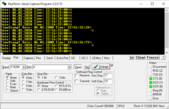
After the falling edge appears, an interrupt occurs and it’s printed to serial. Simple 🙂 You can find the full example code here.
Tamper in STM32F4
I already mentioned this function in the context of the F1 articles because it’s present there as well. Its operation consists in clearing the backup registers after detecting an edge on a dedicated pin. It’s a kind of anti-burglar. When someone tries to break into a device and opens the enclosure, we can automatically erase sensitive data from battery-backed registers.
To set Tamper, it’s enough to check the appropriate box in Cube.
Here too, a configured pin will appear on the microcontroller diagram.
And of course, new options appeared in the RTC configuration
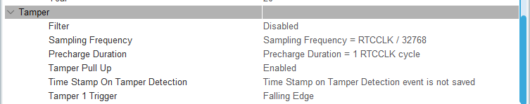
These are mainly pin behavior options.
- Filter – you can decide on which edge the registers will be cleared.
- Sampling Frequency – how often the pin should be checked. The visible setting means checking the pin once per second.
- Precharge Duration – precharging the pin to a high state. A kind of pull-up without a resistor, if I understand it correctly. Note – to PC13 in BlackPill an LED is connected, which will immediately discharge this charge!
- Tamper PullUp – whether to use this precharge.
- Time Stamp On Tamper Detection – a combination with Time Stamp
- Tamper 1 Trigger – which edge the Tamper module should react to.
The event that triggers Tamper not only erases the contents of the backup registers, but it can also trigger an interrupt. In the example I use it to set Tamper again.
  while (1)
  {
	  HAL_RTC_GetTime(&hrtc, &RtcTime, RTC_FORMAT_BIN);
	  Milliseconds = ((RtcTime.SecondFraction-RtcTime.SubSeconds)/((float)RtcTime.SecondFraction+1) * 100);
	  HAL_RTC_GetDate(&hrtc, &RtcDate, RTC_FORMAT_BIN);

	  if(RtcTime.Seconds != CompareSeconds)
	  {
		  MessageLen = sprintf((char*)Message, "Date: %02d.%02d.20%02d Time: %02d:%02d:%02d:%02d\n\r", RtcDate.Date, RtcDate.Month, RtcDate.Year, RtcTime.Hours, RtcTime.Minutes, RtcTime.Seconds, Milliseconds);
		  HAL_UART_Transmit(&huart2, Message, MessageLen, 100);
		  CompareSeconds = RtcTime.Seconds;
	  }

	  if(TamperFlag == 1)
	  {

		  HAL_RTCEx_GetTimeStamp(&hrtc, &RtcTimeTimeStamp, &RtcDateTimeStamp, RTC_FORMAT_BIN);
		  Milliseconds = ((RtcTime.SecondFraction-RtcTimeTimeStamp.SubSeconds)/((float)RtcTime.SecondFraction+1) * 100);

		  MessageLen = sprintf((char*)Message, "Tamper detected at Time Stamp %02d.%02d.20%02d Time: %02d:%02d:%02d:%02d!\n\r",RtcDateTimeStamp.Date, RtcDateTimeStamp.Month, RtcDateTimeStamp.Year,
				  RtcTimeTimeStamp.Hours, RtcTimeTimeStamp.Minutes, RtcTimeTimeStamp.Seconds, Milliseconds);
		  HAL_UART_Transmit(&huart2, Message, MessageLen, 100);

		  MessageLen = sprintf((char*)Message, "Backup Registers cleared:\n\r");
		  HAL_UART_Transmit(&huart2, Message, MessageLen, 100);

		  for(int i = 0; i < BACKUP_COUNT; i++)
		  {
			  uint32_t tmp = HAL_RTCEx_BKUPRead(&hrtc, aBKPDataReg[i]);
			  MessageLen = sprintf((char*)Message, "%X, ", tmp);
			  HAL_UART_Transmit(&huart2, Message, MessageLen, 100);
		  }

		  MessageLen = sprintf((char*)Message, "\n\r");
		  HAL_UART_Transmit(&huart2, Message, MessageLen, 100);

		  MessageLen = sprintf((char*)Message, "Write example data to regs:\n\r");
		  HAL_UART_Transmit(&huart2, Message, MessageLen, 100);

		  for(int i = 0; i < BACKUP_COUNT; i++)
		  {
			  HAL_RTCEx_BKUPWrite(&hrtc, aBKPDataReg[i], (i * 32));
			  uint32_t tmp = HAL_RTCEx_BKUPRead(&hrtc, aBKPDataReg[i]);
			  MessageLen = sprintf((char*)Message, "%X, ", tmp);
			  HAL_UART_Transmit(&huart2, Message, MessageLen, 100);
		  }

		  MessageLen = sprintf((char*)Message, "\n\rWait for Tamper\n\r\n\r");
		  HAL_UART_Transmit(&huart2, Message, MessageLen, 100);

		  RTC_TamperSet();
		  TamperFlag = 0;
	  }

	  if(GPIO_PIN_RESET == HAL_GPIO_ReadPin(TEST_GPIO_Port, TEST_Pin))
	  {
		 while(GPIO_PIN_RESET == HAL_GPIO_ReadPin(TEST_GPIO_Port, TEST_Pin))
		 {}
		 SetRTC();
	  }
    /* USER CODE END WHILE */

    /* USER CODE BEGIN 3 */
  }
In the main loop I set the registers and wait for the Tamper event. I connected a button and an external Pull Up to the board so that it works correctly (not that precharged Pull Up, because there’s an LED). After the Tamper interrupt occurs, I only set a flag, and then after checking it I print the register contents, fill them again, and set Tamper once more.
Here is the result:
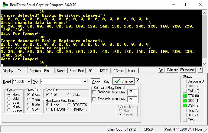
The registers are nicely cleared 🙂 You can find the full example code here.
Tamper + Time Stamp in STM32F4
In the Tamper setup there was something like Time Stamp On Tamper Detection. During normal Tamper operation, we clear the registers and that’s it.
Sometimes, however, there may be a need where you’d like to know a bit more about this break-in. For example, when it happened. That’s exactly what combining these two functions enables – clearing and recording the date and time of the event.
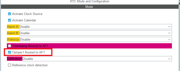
It’s enough to set this one bit in the Tamper configuration to combine these two functions.
Then, in the Tamper handler, it’s enough to read the special Time Stamp registers, which store the information about when it happened and… that’s it 🙂 Two birds with one stone. Simple, right?
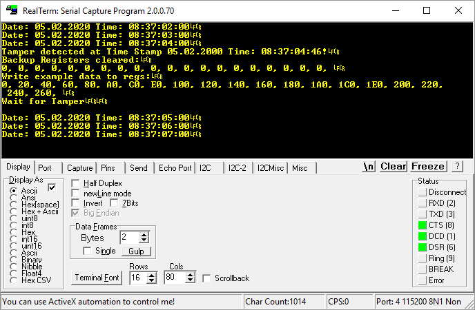
You can find the full example code here.

Summary
As you can see, using the additional features of the built-in RTC is not complicated. Remember that these functions, like the entire clock module, work during battery power. This means that a “break-in” during battery operation is recorded in special registers intended for these functions. This is a very valuable property because we don’t always want the MCU to be running at full speed.
In the next post I’ll cover functions related to waking up the microcontroller and… a human 🙂
You’ll find the full project along with the library as usual on my GitHub: LINK
If you noticed an error, disagree with something, would like to add something important, or simply feel like you’d like to discuss this topic, write a comment. Remember that the discussion should be polite and follow the rules of the Polish language.
Podobne artykuły


0 Comments