In the last article I described the adventures related to the original API provided for the laser distance sensor VL53L0X. I got to the point where I managed to run a single measurement. However, I’d like to relieve the microcontroller a bit so it doesn’t have to wait so long for the measurement to finish. The sensor has an interrupt output pin, so why not use it?

VL53L0X Operating Modes
Our hero can operate in two modes: single measurement (Single measurement) and continuous measurement (Continuous measurement).
In the first one, we as programmers must make sure to start the measurement, wait for it to finish, and read the result.
In continuous mode, measurements are performed all the time, and our task is only to read the measured values.
Naturally, the idea of using an interrupt comes to mind. We get an interrupt every time the sensor finishes a measurement and has the data ready for us. Interestingly, such an interrupt is generated both in single-measurement mode and in continuous mode. The API probably enables the interrupt in the sensor by default in both cases.
Why an interrupt in single mode? First, so we don’t have to wait for the measurement to finish. Second, using single mode will let us measure distance less often. In continuous mode, the sensor goes as fast as the factory allows.
Test platform
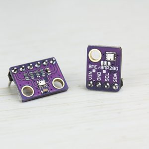
For testing continuous operation I used the same configuration as in the previous post. If you haven’t seen it yet, I encourage you to read it -> Cheap laser distance measurement with the VL53L0X ToF sensor
In a nutshell, I’m using:
- STM32F401CC on a BlackPill board from my store
- STM32CubeIDE v1.1.0
- SM32CubeMX v5.4.0 built into the IDE
- HAL F4 libraries v1.24.2
- The sensor API provided by ST
Working in continuous mode
First, it would be good to check how continuous mode works from the examples. Just like before, I’ll take the example from what is provided in the API.
The code looks like this.
  //
  // VL53L0X init for Continuous Measurement
  //

  VL53L0X_WaitDeviceBooted( Dev );
  VL53L0X_DataInit( Dev );
  VL53L0X_StaticInit( Dev );
  VL53L0X_PerformRefCalibration(Dev, &VhvSettings, &PhaseCal);
  VL53L0X_PerformRefSpadManagement(Dev, &refSpadCount, &isApertureSpads);
  VL53L0X_SetDeviceMode(Dev, VL53L0X_DEVICEMODE_CONTINUOUS_RANGING);

  VL53L0X_StartMeasurement(Dev);
  /* USER CODE END 2 */

  /* Infinite loop */
  /* USER CODE BEGIN WHILE */
  while (1)
  {

	  VL53L0X_Error Status = WaitMeasurementDataReady(Dev);

      if(Status == VL53L0X_ERROR_NONE)
      {
          Status = VL53L0X_GetRangingMeasurementData(Dev, &RangingData);

          // Clear the interrupt
          VL53L0X_ClearInterruptMask(Dev, VL53L0X_REG_SYSTEM_INTERRUPT_GPIO_NEW_SAMPLE_READY);
          VL53L0X_PollingDelay(Dev);
      } else {
          break;
      }

	  if(RangingData.RangeStatus == 0)
	  {
		  MessageLen = sprintf((char*)Message, "Measured distance: %i\n\r", RangingData.RangeMilliMeter);
		  HAL_UART_Transmit(&huart2, Message, MessageLen, 100);
	  }

    /* USER CODE END WHILE */

    /* USER CODE BEGIN 3 */
  }
After setting continuous mode, it’s enough to start the measurement and the machine is rolling. Unfortunately, the example uses active waiting for the measurement to finish. The API does not provide interrupt-based operation out of the box, so an extra function WaitMeasurementDataReady, was added, which actively waits. It’s a pity, because continuous measurement currently looks exactly the same as single measurement, with the only difference being that you don’t have to start the conversion.
You’ll admit it’s pointless, right? So how do you use an interrupt? Of course, you need to take a few small steps 🙂
Using interrupts with the API
Ok. First, move on to configuring the interrupt in Cube. Set the line where the GPIO1 pin from the sensor is connected as an interrupt input. Yes – GPIO1 is the interrupt pin on the VL53L0X.
In my project it’s pin PB3, so I enable it as GPIO_EXTI3. Remember to enable this interrupt in the NVIC configuration.
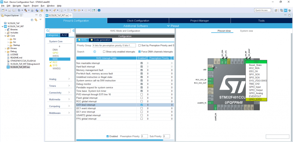
And that’s it for configuration. Generate the code.
Now a very important thing. I don’t know why, but the API enables interrupts in the sensor itself right from the start of its operation. This causes a problem in that the first interrupts appear already during initialization. I didn’t dig into whether they actually use this interrupt during initialization. This is what the initialization procedure itself looks like.
Now, if you have the interrupt enabled in the STM32 before initialization—and you do, because NVIC is always initialized with the interrupt enabled—then there will be a problem. Such a problem that initialization will stop and loop like this.
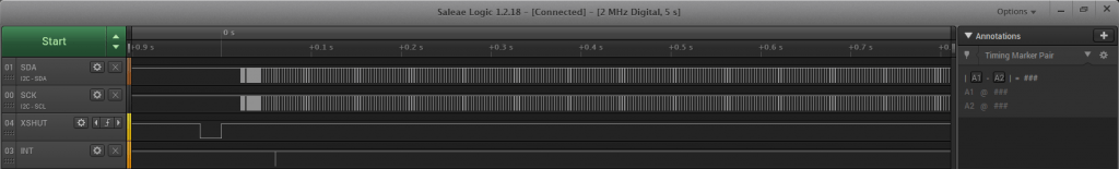
So you need to DISABLE the interrupt for the duration of initialization. Then everything works nicely 🙂
The full initialization will look like this.
  //
  // VL53L0X init for Single Measurement
  //

  HAL_NVIC_DisableIRQ(EXTI3_IRQn);

  VL53L0X_WaitDeviceBooted( Dev );
  VL53L0X_DataInit( Dev );
  VL53L0X_StaticInit( Dev );
  VL53L0X_PerformRefCalibration(Dev, &VhvSettings, &PhaseCal);
  VL53L0X_PerformRefSpadManagement(Dev, &refSpadCount, &isApertureSpads);
  VL53L0X_SetDeviceMode(Dev, VL53L0X_DEVICEMODE_CONTINUOUS_RANGING);
  VL53L0X_StartMeasurement(Dev);

  HAL_NVIC_EnableIRQ(EXTI3_IRQn);
Interrupt handling
Alright, but now how do you write the interrupt handler? Look in main at what is executed.
	  VL53L0X_Error Status = WaitMeasurementDataReady(Dev);

      if(Status == VL53L0X_ERROR_NONE)
      {
          Status = VL53L0X_GetRangingMeasurementData(Dev, &RangingData);

          // Clear the interrupt
          VL53L0X_ClearInterruptMask(Dev, VL53L0X_REG_SYSTEM_INTERRUPT_GPIO_NEW_SAMPLE_READY);
          VL53L0X_PollingDelay(Dev);
      } else {
          break;
      }
First we wait for data – the interrupt is supposed to take care of that. Next we fetch the data, clear the interrupt in the sensor, and wait (??? that’s how it was in the example :D).
It’s enough to move the data readout and clearing of the interrupt flag into the interrupt handler and it should work, right? The whole EXTI3 interrupt handler will therefore look like this.
void HAL_GPIO_EXTI_Callback(uint16_t GPIO_Pin)
{
	if(GPIO_Pin == TOF_INT_Pin)
	{
		VL53L0X_GetRangingMeasurementData(Dev, &RangingData);
		VL53L0X_ClearInterruptMask(Dev, VL53L0X_REG_SYSTEM_INTERRUPT_GPIO_NEW_SAMPLE_READY);
		TofDataRead = 1;
	}
}
I also added a helper variable so that I don’t print tons of data in main, but only when it has been read.
So you can remove continuous-mode handling from the main loop, because basically it’s now all in the interrupt handler. In the loop you only check whether there was a new sample and print it to the terminal.
  while (1)
  {

	  if(TofDataRead == 1)
	  {
		MessageLen = sprintf((char*)Message, "Measured distance: %i\n\r", RangingData.RangeMilliMeter);
		HAL_UART_Transmit(&huart2, Message, MessageLen, 100);
		TofDataRead = 0;
	  }
    /* USER CODE END WHILE */

    /* USER CODE BEGIN 3 */
  }
Does it work?
– Sir, you sure wrote a lot, but does it work?
– Sir, you bet it does!
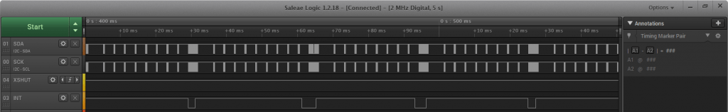
Now you just run the code and data will start flying into the terminal. Ok, you’ll say it was the same in single-shot mode. Let’s see what’s happening on the wires.
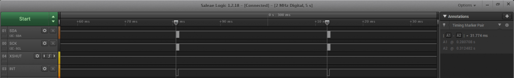
Beautiful! The microcontroller only stirs the I²C interface when a new sample is ready in the sensor. That’s exactly what we wanted! 🙂
The time between interrupts is just under 32 milliseconds. It was similar in single mode.
Interrupt handling
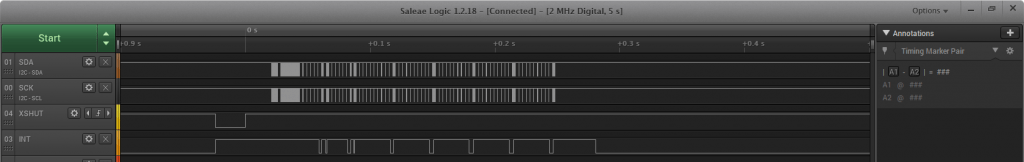
Let’s also see what the interrupt routine itself looks like and how long it takes.
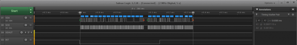
It takes about 638 µs at an I²C clock speed of 400 kHz. Quite a bit of data moves over the bus.

Summary
Interrupt-driven handling in continuous mode significantly relieves the microcontroller. However, successive samples still arrive at intervals of about 30 milliseconds. It’s not a speed demon.
Since the last post I’ve been getting tons of questions about this sensor. Most often, questions appear about comparing such a laser sensor with the classic HC-SR04 ultrasonic sensor. I thought it would be cool to do such a test 🙂 If you have any suggestions under what conditions to test both sensors, write in a comment.
As usual, you can find the full project along with the library on my GitHub: link
If you noticed any mistake, disagree with something, would like to add something important, or simply feel like you’d like to discuss this topic, write a comment. Remember that the discussion should be polite and in accordance with the rules of the Polish language.
Podobne artykuły


0 Comments